Connector that automatically latch-locks a flat conducting wire

a technology of conducting wire and automatic latching, which is applied in the direction of coupling/case, coupling device connection, electrical apparatus, etc., can solve the problem that the design engineer may not be able to determine where to dispose of indented notches on the conducting wire, and the user may misjudgment that the latching-locking has been completed

Active Publication Date: 2021-05-11
P-TWO INDUSTRIES INC
View PDF7 Cites 3 Cited by
  • Summary
  • Abstract
  • Description
  • Claims
  • Application Information

AI Technical Summary

Benefits of technology

[0006]The second objective of the present invention is to provide said connector capable of driving the first elastic locking part and the second elastic locking part either respectively or concurrently, in order to accommodate different user scenarios.
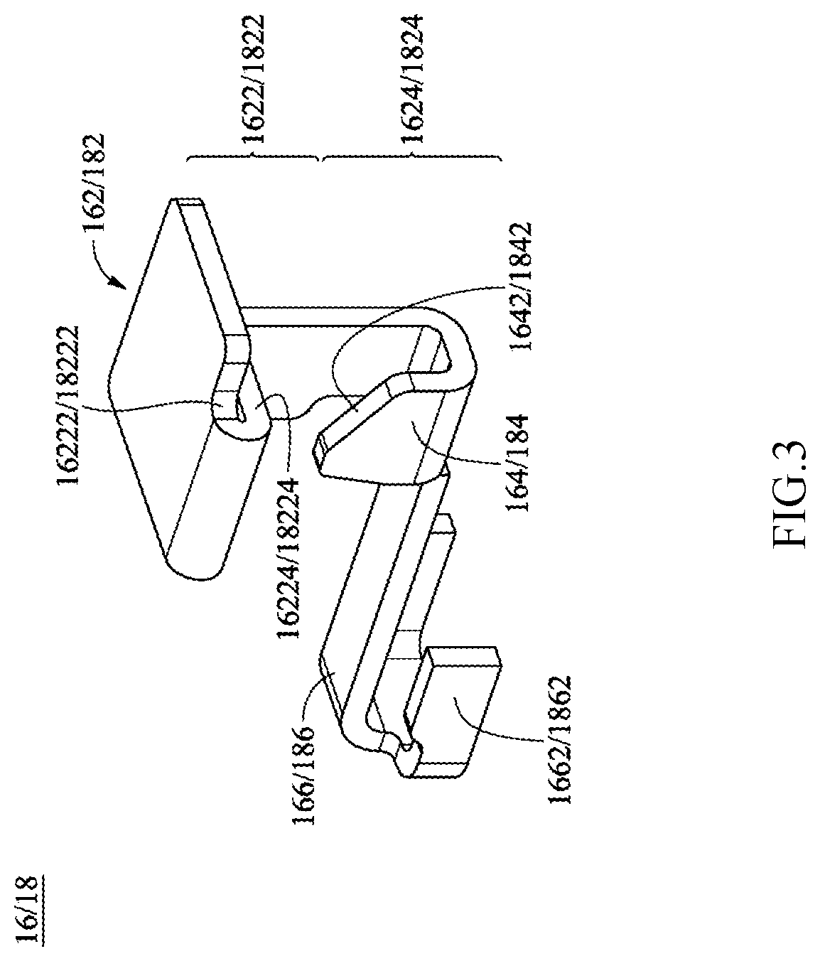
[0007]The third objective of the present invention is to provide said connector wherein a locking protrusion of the elastic locking part is disposed on the lower portion of the operating part and enables the lower portion to face the same force direction as upper portion of the operating part, in order to achieve zero direct force loss.
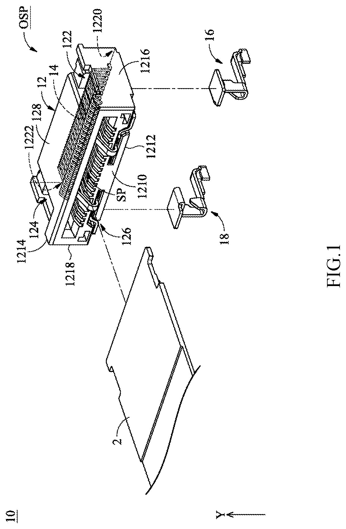
[0009]Compared to the prior art, the present invention provides a connector for flat conducting wires, enabling the conducting wires to be automatically latch-locked in the accommodating space of the connector and electrically connected to the terminal inside the accommodating space; in addition, by means of exerting an external force on the upper portion of the operating part which is outside the accommodating space of the connector, the lower portion of the operating part can be directly driven (i.e. forming the locking protrusion), achieving zero or close to zero loss of the external force exerting on the locking protrusion.
[0010]Compared to conventional connectors wherein the insertion depth of a flat conducting wire must exceed the operating part (i.e. a specific pre-determined depth) to perform automatic latch-locking, the locking protrusions of the present invention are close to the insertion opening of the casing, particularly to the lower portion of the operating parts, thereby effectively adjusting the depth into the casing rather than being limited to a particular depth to achieve the efficacy of the automatic latch-locking.
[0011]Moreover, because the locking protrusions of the present invention directly correspond to the upper portion of the operating parts, a user can easily determine the inserted depth of the flat conducting wire required to achieve the efficacy of automatic latch-locking.

Problems solved by technology

However, the conventional connector with automatic latch-lock feature, due to its structural design, causes uncertainty for a user as to the exact location of the locking protrusions, as other than waiting for sound generated from contacting the locking protrusion, completion of automatic latch-locking can not be anticipated through visual observation, thus leaving the possibility of misjudgment by a user that latching-locking has been completed.
Moreover, design engineers may not be able to determine where to dispose indented notches on a conducting wire unless specifications of the corresponding connector are provided.
In addition, as the locking protrusions are generally located near the end, automatic latch-locking malfunction may easily arise in case of elastic arm fatigue or insufficient elastic force.

Method used


Image

  • Connector that automatically latch-locks a flat conducting wire
  • Connector that automatically latch-locks a flat conducting wire
  • Connector that automatically latch-locks a flat conducting wire

Examples


Embodiment Construction

[0016]In order to better understand this invention, its content and the efficacy it can achieve, the invention is explained with the attached figures, and the following is a detailed description of the embodiments. The schematics used in the drawings are only for the purpose of illustration and complementation. It is not intended to be a true proportion and precise configuration of the implementation of the present invention. Therefore, it would not be proper to interpret the proportion and configuration of the illustrations as such, and to limit the scope of rights and actual usage of this invention.

[0017]The advantages and characteristic features of the present invention as well as the achieved technology use the reference implementation and all the attached figures to conduct a more in depth description and be more easily understandable; moreover the present invention can be realized in different shapes, therefore it should not be understood as limited to the implementation descr...


PUM


Abstract

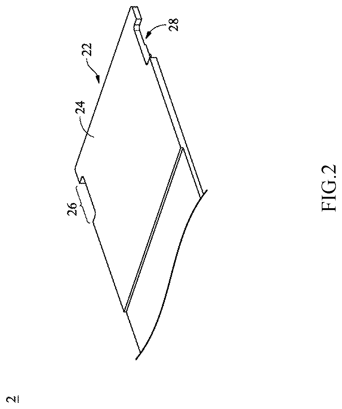
The present invention discloses a connector for flat conducting wires that is directed into the insertion opening, the front end comes in contact with the first locking protrusion and the second locking protrusion of the connector, respectively causing the first elastic arm and the second elastic arm to deform, thereby causing the first operating part and the second operating part to move towards the third surface until the indented notches correspond to the first locking protrusion and the second locking protrusion, which subsequently causes the first elastic arm and the second elastic arm to return to their former position by means of elastic force, latch-locking the front end of the flat conducting wire in the accommodating space, and through exerting an external force on the upper portion of the first operating part and the upper portion of the second operating part to unlatch and separate from the accommodating space.

Description

FIELD OF THE INVENTION[0001]The present invention relates to a connector, particularly, to a connector that automatically latch-locks a flat conducting wire.BACKGROUND OF THE INVENTION[0002]A conventional connector acts as an intermediary connecting component which facilitates the connection of a conducting wire to a circuit board, and with its advantage of no soldering the conducting wire to the circuit board required, a user can easily perform electrical connection through plugging.[0003]In order for stable and firm contact between a connector and a conducting wire, various types of connection methods have been developed, e.g. via automatic latch-locking to readily connect the connector and the conducing wire without loosening off, where in the aforementioned motion the connecting wire is automatically latched during the course of insertion into the connector to ensure connection of the two. However, the conventional connector with automatic latch-lock feature, due to its structur...

Claims


Application Information

Patent Timeline
Patent Type & Authority Patents(United States)
IPC IPC(8): H01R12/77H01R13/627
CPCH01R12/774H01R13/6275H01R12/77H01R13/46H01R13/627H01R13/6273
Inventor LIN, SHIEN-CHANG
Owner P-TWO INDUSTRIES INC
Why Eureka
Try Eureka