Liquid container lid assembly for controlled liquid delivery

a liquid container and lid technology, applied in the direction of lids, packaging, removable lids/covers, etc., can solve the problems of limited knowledge of the means of cooling hot beverages prior to consumption by way of lid construction or assembly, and achieve the effects of enhancing heat transfer, enhancing liquid redirection, and enhancing liquid compartmentalization

Active Publication Date: 2021-05-18
LEA SAVENOK 2003 TRUST
View PDF1 Cites 0 Cited by
  • Summary
  • Abstract
  • Description
  • Claims
  • Application Information

AI Technical Summary

Benefits of technology

[0021]The lower lid construction preferably comprises or provides a knob-receiving groove and the upper lid constructions preferably comprise or provide a downwardly extending knob. The downwardly extending knob is translatably receivable in the knob-receiving groove when the upper lid constructions are nested down atop the upper-receiving depression. The knob-receiving groove and the downwardly extending knob are together cooperable for guiding movement of the upper lid constructions relative to the lower lid construction for enabling the user to more effectively control liquid egression from the outfitted liquid container.
[0022]The downwardly extending knob preferably comprises a certain knob-girth and the knob-receiving groove preferably comprises opposed groove ends and a central section intermediate the opposed groove (or tight) ends. At least one of the opposed groove ends is structurally configured for resistively receiving the knob-girth of the knob for providing haptic feedback to the user that the downwardly extending knob is entering the at least one of the opposed groove ends. The opposed groove ends and the downwardly extending knob provide movement stop structure or upper lid construction stop structure associated with either the fully open lid configuration or the fully closed lid configuration. Thus, the haptic feedback informs the user of the user's fully open or fully closed lid configuration.
[0023]Although it is contemplated that at least one of the groove ends be configured for resistively receiving the knob-girth for providing haptic feedback to the user that the downwardly extending knob is entering either of the opposed groove ends it is preferable that each of the opposed groove ends are so configured for informing the user of the user's fully open or fully closed lid configuration. The groove end associated with the fully closed configuration is preferably outfitted with an air-letting aperture, which air-letting aperture basically functions to enhance pressure equalization and enhanced liquid egression via the lid assemblies when the lid assemblies are in a select open configuration according to state of the art principles. It is believed inventive, however, to provide a downwardly extending knob that covers the air-letting aperture when received in the groove end associated with the fully closed configuration for restricting pressure equalization and preventing liquid egression via the lid assemblies.
[0025]The flanking portion diversion delays liquid delivery and enhances heat transfer from the liquid prior to liquid egression via the primary liquid outlet. The raised formation may further preferably comprise upper formation surfacing, which surfacing is parallel to the convex lower portion surfacing and the primary liquid outlet flanking portions comprise upper flank portions that extend obliquely relative to the upper formation surfacing for enhancing redirection of liquid toward the primary liquid outlet. The at least one liquid-letting aperture preferably comprises a raised peripheral ridge, which raised peripheral ridge has upper ridge apex surfacing for engaging the lower portion surfacing during movement of the upper lid constructions relative to the lower lid construction for enhancing compartmentalization of liquid within the outfitted liquid container.
[0026]Similarly, the primary liquid outlet is preferably bordered by a downwardly extending ridge formation. The downwardly extending ridge formation has lower ridge apex surfacing for engaging the upper portion surfacing during movement of the upper lid constructions relative to the lower lid construction for enhancing compartmentalization of liquid within the outfitted liquid container. The lid-to-container fastening groove radially and uniformly extends about a primary lid axis, and the upper-receiving depression radially and uniformly extends about a depression axis. The depression axis is parallel to the primary lid axis and thus the depression is preferably and centrally offset relative to the groove. The upper lid constructions are rotatably nestable atop the lower lid construction for enabling a user to rotate the upper lid constructions about an axis relative to the lower lid construction for selectively orienting the primary lid outlet in superior adjacency to the at least one liquid-letting aperture.
[0027]The lower lid construction preferably comprises an edge-receiving groove, and the upper lid constructions preferably comprises a peripheral outer edge. The peripheral outer edge is preferably and rotatably received in the edge-receiving groove for rotatably attaching the upper lid constructions to the lower lid construction. The upper lid constructions may be preferably constructed from or comprise a resilient material. Thus, the upper lid constructions may be actuated and nested or actuably nested atop the upper-receiving depression for enhancing fitted engagement of the upper lid constructions relative to the lower lid construction via the resiliently directed return forces of the material construction of the upper lid constructions.

Problems solved by technology

The art relating to means for cooling hot beverages prior to consumption by way of a lid construction or assembly is a bit more limited.

Method used


Image

  • Liquid container lid assembly for controlled liquid delivery
  • Liquid container lid assembly for controlled liquid delivery
  • Liquid container lid assembly for controlled liquid delivery

Examples


Embodiment Construction

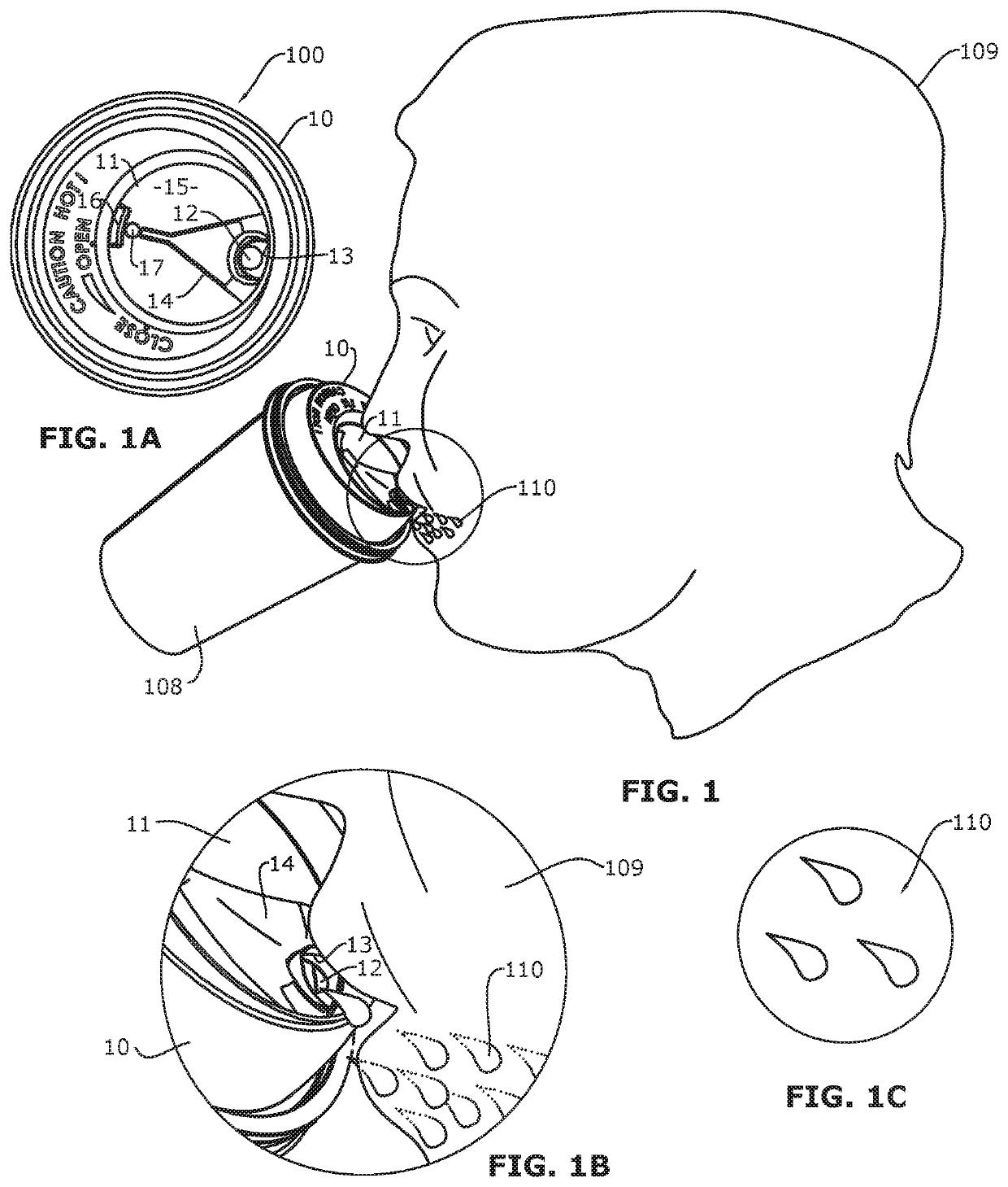
[0111]Referring now to the drawings with more specificity, FIGS. 1-1C depict a series of images that attempt to depict a user 109 drinking from a liquid container 108 outfitted with a first alternative lid assembly with nested bowl or insert feature according to the present invention with the first alternative lid assembly 100 shown in a fully open position or configuration. The fully open position is perhaps best shown or depicted in FIG. 1A. Outletting liquid 110 is depicted in FIG. 1B. The liquid volume as at 110 being outlet is diagrammatically or schematically depicted in FIG. 1C with three relatively large drops (as compared to drop sizes shown in FIGS. 2C and 3C) in an attempt to denote a maximum flow rate of the beverage or liquid when a lower aperture 12 (i.e. a first liquid-letting aperture) formed in the lower lid construction 10 is in alignment with an upper aperture or primary liquid-letting outlet 13 formed in the upper lid construction 11.

[0112]The series of images pr...


PUM


Abstract

A liquid container lid assembly enables a user to more effectively control liquid egression from a liquid container as outfitted with the lid assembly. The lid assembly includes a lower lid construction and an upper lid construction. The lower lid construction includes an upper-receiving depression having at least one liquid-letting aperture. The lower lid construction is removably attachable to an upper container rim of a liquid container and the upper-receiving depression includes concave upper portion surfacing. The upper lid construction is nestable in superior adjacency to the upper-receiving depression and includes a lower-opposing portion and a primary liquid outlet. The lower-opposing portion includes convex lower portion surfacing, which convex lower portion surfacing mimics the concave upper portion surfacing for eliminating gaps therebetween. The primary liquid outlet is orientable in superior adjacency to the lower lid construction for selectively outletting liquid received in an assembly-outfitted liquid container.

Description

PRIOR HISTORY[0001]This application is a US National Stage Application under 35 USC § 371 from International Patent Application No. PCT / US2017 / 033389, which application was filed in the United States Patent and Trademark Office (USPTO) as the International Receiving Office on 18 May 2017 and claimed the benefit of or priority to U.S. Provisional Patent Application No. 62 / 338,503 filed in the USPTO on 18 May 2016.FIELD OF THE INVENTION[0002]The present invention relates generally to liquid container lid assembly for outfitting hot liquid or hot consumable containers. More particularly, the present invention relates to container lid assemblies for outfitting a hot consumable liquid containers for enabling enhanced control of liquid delivery via compartmentalization and heat transfer from lid-diverted or compartmentalized liquid prior to liquid egression.BRIEF DESCRIPTION OF THE PRIOR ART[0003]The broad field of lids for hot beverage or liquid consumable containers and hot beverage or ...

Claims


Application Information

Patent Timeline
Patent Type & Authority Patents(United States)
IPC IPC(8): B65D47/04B65D47/26B65D43/02B65D51/18B65D43/00
CPCB65D47/265B65D43/00B65D43/02B65D43/0208B65D51/18B65D2543/00046B65D2543/00092B65D2543/00296B65D2543/00509B65D2543/00537B65D2543/00555B65D2543/00731B65D2543/00796B65D47/261B65D2205/02B65D51/1611
Inventor SAVENOK, PAVEL
Owner LEA SAVENOK 2003 TRUST
Why Eureka
Try Eureka