
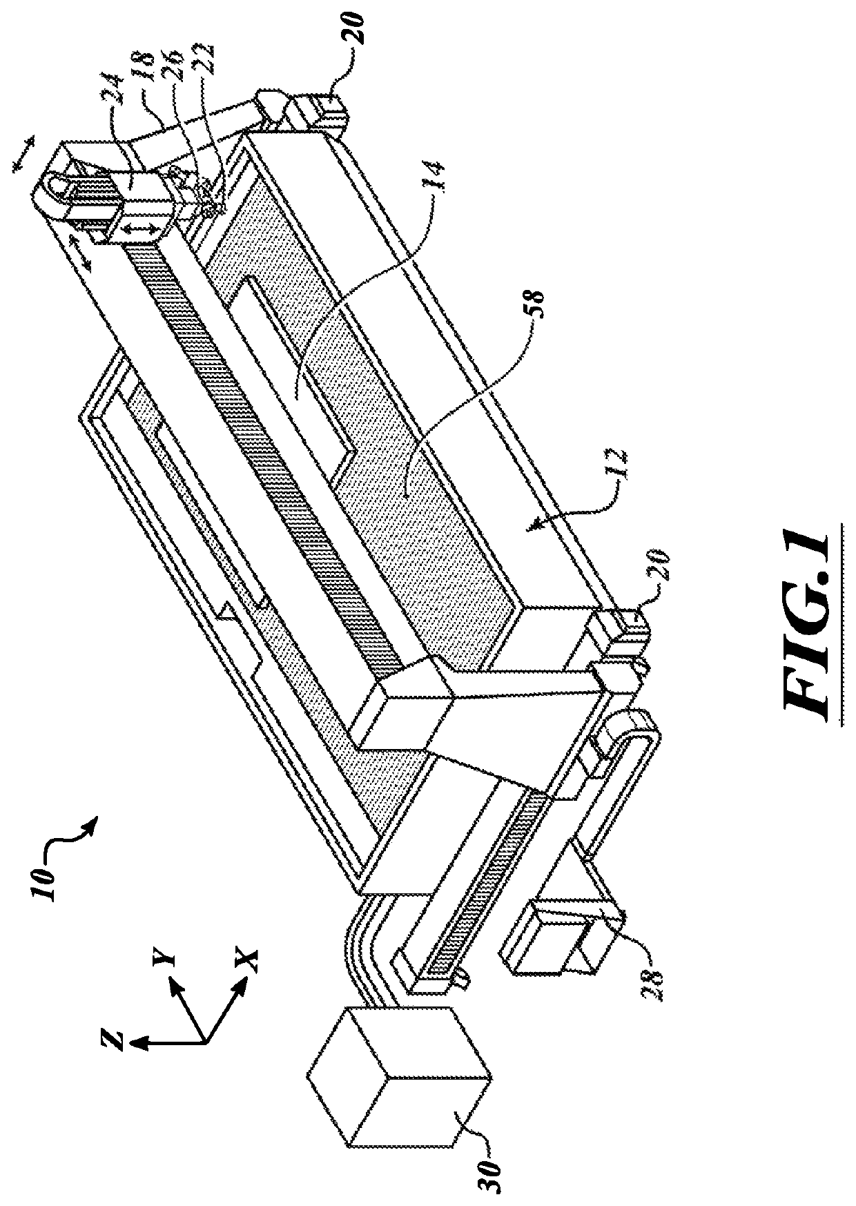
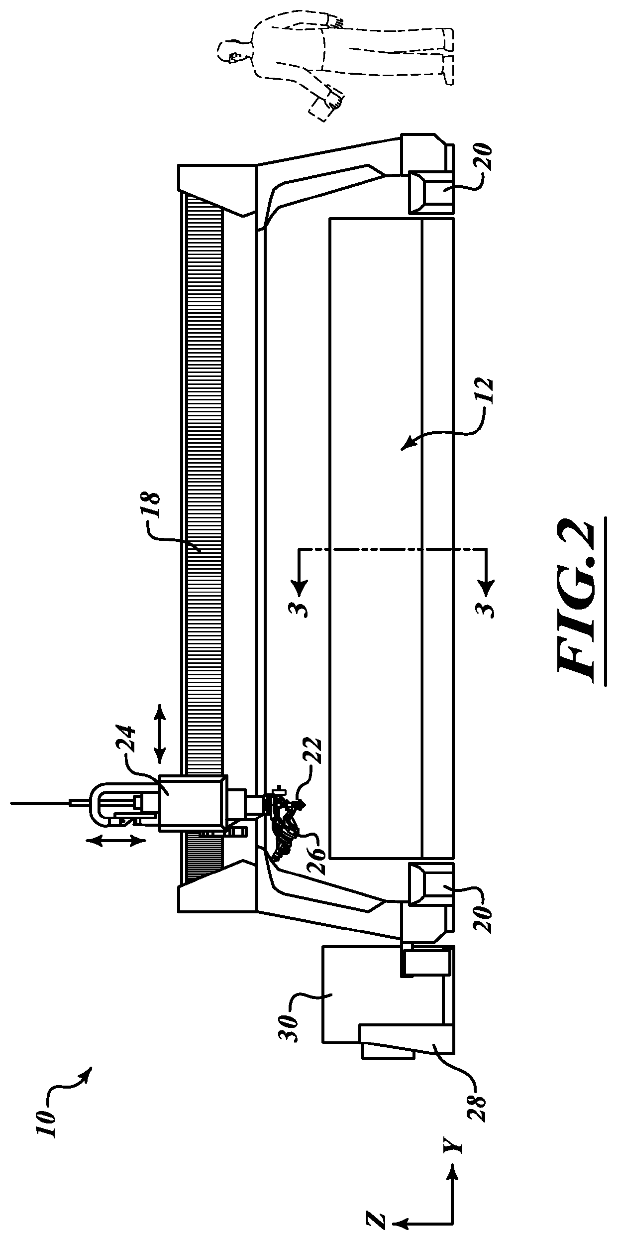
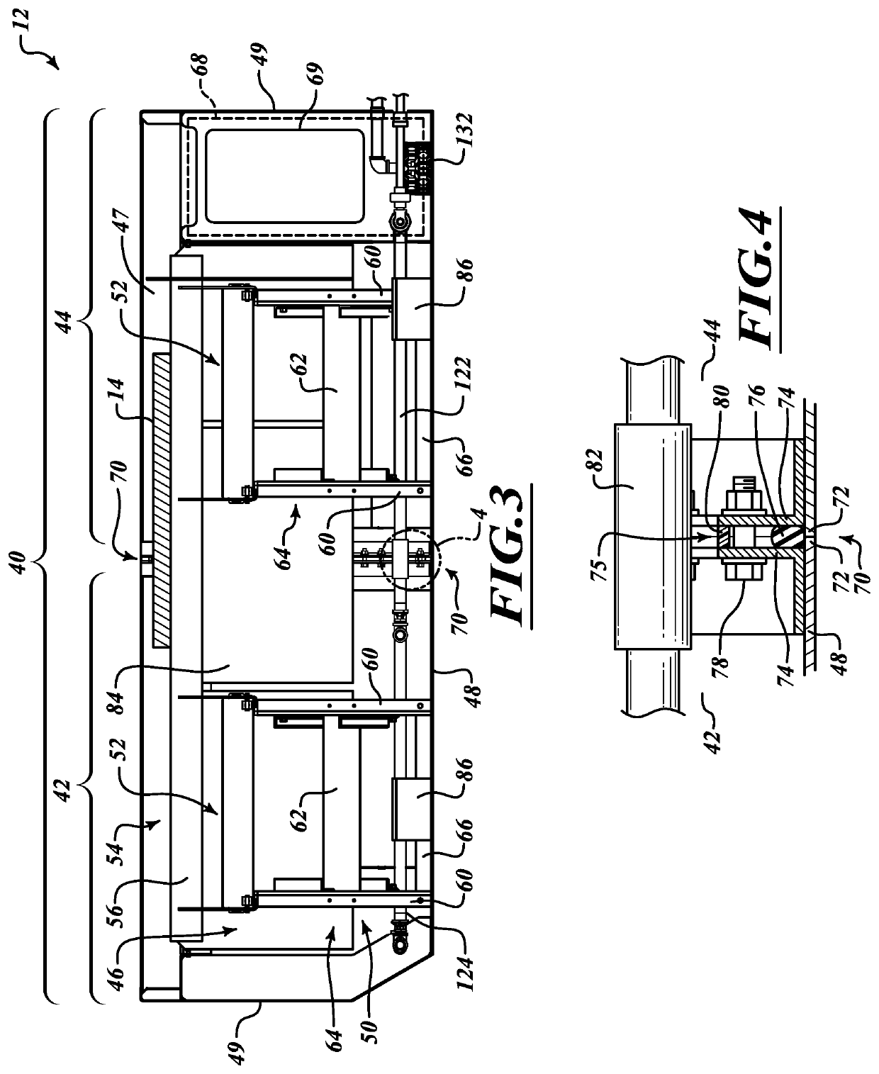
Catcher tank assembly of waterjet cutting system

a technology catcher tank, which is applied in the field of catcher tank assembly of waterjet cutting system, can solve the problems of limited adaptability to changing conditions and new applications, and achieve the effects of enhancing the assembly the related system, facilitating shipment, and reducing the size of the catcher tank

Active Publication Date: 2021-06-29
FLOW INT
View PDF42 Cites 0 Cited by
  • Summary
  • Abstract
  • Description
  • Claims
  • Application Information

AI Technical Summary

Benefits of technology

[0004]Embodiments described herein provide catcher tank assemblies and waterjet cutting systems having particularly versatile form factors to enable the construction of catcher tank assemblies and waterjet cutting systems of divergent sizes and capabilities. Components of the catcher tank assemblies may include modular units to facilitate shipment and enhance assembly of the catcher tank and related systems.

Problems solved by technology

Conventional catcher tanks are robust structures which can be particularly burdensome to fabricate and / or transport, and which are limited in their ability to adapt to changing conditions and new applications.

Method used


Image

  • Catcher tank assembly of waterjet cutting system
  • Catcher tank assembly of waterjet cutting system
  • Catcher tank assembly of waterjet cutting system

Examples


Embodiment Construction

[0029]In the following description, certain specific details are set forth in order to provide a thorough understanding of various disclosed embodiments. However, one of ordinary skill in the relevant art will recognize that embodiments may be practiced without one or more of these specific details. In other instances, well-known structures associated with waterjet systems and catcher tank assemblies may not be shown or described in detail to avoid unnecessarily obscuring descriptions of the embodiments. For instance, it will be appreciated by those of ordinary skill in the relevant art that a high-pressure fluid source and an abrasive source may be provided to feed high-pressure fluid and abrasives, respectively, to a cutting head of the waterjet system to facilitate high-pressure abrasive waterjet cutting of workpieces supported by the catcher tank assemblies described herein. As another example, well known control systems and drive components may be integrated into the waterjet c...


PUM

PropertyMeasurementUnit
lengthaaaaaaaaaa
thicknessaaaaaaaaaa
widthaaaaaaaaaa

Abstract

A catcher tank assembly is provided for a waterjet cutting machine. The catcher tank assembly includes a catcher tank having a plurality of tank sections detachably coupleable together in a side-by-side manner to collectively define a catcher tank having a desired configuration. The catcher tank assembly further includes a workpiece support system detachably coupleable to an interior cavity of the catcher tank. The workpiece support system may include a plurality of workpiece support modules arrangeable in an array to support a workpiece platform of the waterjet cutting machine. The workpiece platform may be formed, for example, by a series of slats supported transversely to parallel rows of the workpiece support modules. Methods and systems which relate to or include the aforementioned catcher tank assembly are also provided.

Description

BACKGROUNDTechnical Field[0001]This disclosure relates to a catcher tank assembly of a waterjet cutting system, and in some embodiments, is directed to a catcher tank assembly having a particularly versatile form factor to enable the construction of catcher tank assemblies of divergent sizes and capabilities.Description of the Related Art[0002]High-pressure fluid jets, including high-pressure abrasive waterjets, are used to cut a wide variety of materials in many different industries. Systems for generating high-pressure waterjets and abrasive waterjets (collectively “waterjets”) are currently available, such as, for example, the Mach 4™ 5 axis waterjet system manufactured by Flow International Corporation, the assignee of the present invention. Other examples of waterjet cutting systems are shown and described in Flow's U.S. Pat. No. 5,643,058, which is incorporated herein by reference in its entirety. In such systems, high-pressure fluid, typically water, flows through an orifice ...

Claims


Application Information

Patent Timeline
Patent Type & Authority Patents(United States)
IPC IPC(8): B26F3/00B26D7/01B65D88/00
CPCB26F3/008B65D88/005B26D7/01B26F3/004Y10T29/49826Y10T83/364
Inventor KNAUPP, MICHAELMEYER, ANDREASCRAIGEN, STEVEN J.MANN, ROBERT J.HASHISH, MOHAMED A.ULLRICH, ECKHARDT R.LOOFBOUROW, THOMAS R.
Owner FLOW INT
Learn More