Continuously variable power-split transmission

a technology of power-split transmission and continuously variable power, which is applied in the direction of mechanical equipment, transportation and packaging, etc., can solve the problems of reducing the transmission efficiency compared to a purely mechanical transmission, and achieve the effect of improving continuously variable power-split transmission, reducing reactive power or even avoiding i

Active Publication Date: 2021-06-29
ZF FRIEDRICHSHAFEN AG
View PDF13 Cites 0 Cited by
  • Summary
  • Abstract
  • Description
  • Claims
  • Application Information

AI Technical Summary

Benefits of technology

[0007]It is the object of the invention to provide an improved continuously variable power-split transmission in which a reactive power is reduced or even avoided.

Problems solved by technology

As a result of the system, during operation the continuously variable hydrostatic-mechanical power-split transmission provides, via the hydrostatic power path, a reduced level of transmission efficiency compared to a purely mechanical transmission.

Method used


Image

  • Continuously variable power-split transmission
  • Continuously variable power-split transmission
  • Continuously variable power-split transmission

Examples


first embodiment

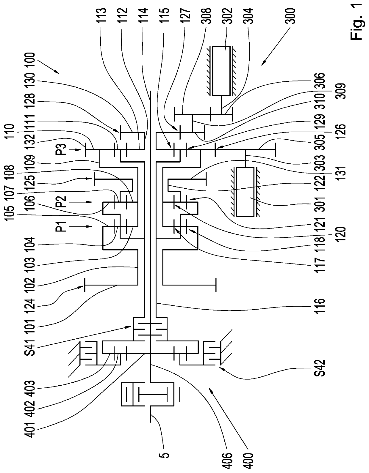
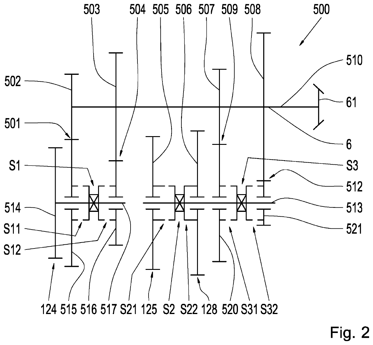
[0057]A combination of the change-speed gearbox 500 shown in FIG. 2 with the arrangement described in FIG. 1 forms a continuously variable power-split transmission 1 and is shown in FIG. 3. The fixed gear 101 of the planetary gear mechanism arrangement 100 is in engagement with the fixed gear 514 and forms therewith the gearwheel pairing 124. The fixed gear 131 of the planetary gear mechanism arrangement 100 is in engagement with the first idler gear 505 and forms therewith the gearwheel pairing 125. The fixed gear 130 is in engagement with the second idler gear 506 and forms therewith the gearwheel pairing 128.

[0058]A modification of the change-speed gearbox 500 shown in FIG. 2 is shown in FIG. 4. The change-speed gearbox 600 shown in FIG. 4 differs from the change-speed gearbox 500 in that the gearwheel pairing 501 is not present. In other words, the change-speed gearbox 600 merely has a single idler gear 516 rather than the first idler gear 515 and the first fixed gear 502 of th...

second embodiment

[0059]A combination of the change-speed gearbox 600 shown in FIG. 4 with the arrangement described in FIG. 1 forms a continuously variable power-split transmission 2 and is shown in FIG. 5. The fixed gear 101 of the planetary gear mechanism arrangement 100 is in engagement with the fixed gear 514 and forms therewith the gearwheel pairing 124. The fixed gear 131 of the planetary gear mechanism arrangement 100 is in engagement with the first idler gear 505 and forms therewith the gearwheel pairing 125. The fixed gear 130 is in engagement with the second idler gear 506 and forms therewith the gearwheel pairing 128.

[0060]A modification of the arrangement shown in FIG. 1 is shown in FIG. 6. The planetary gear mechanism arrangement 800 differs from the planetary gear mechanism arrangement 100 shown in FIG. 1 in that the input shaft 816 is configured as a solid shaft. Additionally, no reverse gear mechanism is provided on the input side but the transmission input shaft is coupled to the i...

third embodiment

[0063]A combination of the change-speed gearbox 700, shown in FIG. 7, and the reverse gear mechanism 1000 with the arrangement described in FIG. 6 forms a continuously variable power-split transmission 3 and is shown in FIG. 8. The fixed gear 101 of the planetary gear mechanism arrangement 800 is in engagement with the fixed gear 514 and forms therewith the gearwheel pairing 124. The fixed gear 131 of the planetary gear mechanism arrangement 800 is in engagement with the first idler gear 505 and forms therewith the gearwheel pairing 125. The fixed gear 130 is in engagement with the second idler gear 506 and forms therewith the gearwheel pairing 128.

[0064]FIG. 9 shows a continuously variable power-split transmission 4 according to a fourth embodiment. The transmission 4 according to the fourth embodiment differs from the transmission 3 according to the third embodiment in that the change-speed gearbox is of nested design in order to save constructional space. According to the fourth...


PUM


Abstract

A continuously variable power-split transmission having a planetary gear mechanism arrangement. The planetary gear mechanism arrangement has three planetary gear sets, an input shaft and three output shafts. Furthermore, the transmission has a change-speed gearbox connected to the output shafts, a reverse gear mechanism and a variator. Each of the three planetary gear sets is assigned a respective output shaft. The input shaft is operatively connected in each of the three planetary gear sets via a respective gearwheel pairing to a respective output shaft. The transmission can be shifted by the change-speed gearbox and the reverse gear mechanism into at least eight driving ranges. The variator varies a transmission ratio of the transmission within the driving ranges in a continuously variable manner. The variator is continuously operatively connected to a single one of the three planetary gear sets.

Description

[0001]This application is a National Stage completion of PCT / EP2018 / 081583 filed Nov. 16, 2018, which claims priority from German patent application serial no. 10 2017 222 596.3 filed Dec. 13, 2017.FIELD OF THE INVENTION[0002]The present invention relates to a continuously variable power-split transmission for a working machine. More specifically, the present invention relates to a continuously variable power-split transmission having a planetary gear mechanism arrangement, a change-speed gearbox and a variator.BACKGROUND OF THE INVENTION[0003]Working machines, such as for example construction or agricultural machines, are increasingly configured with continuously variable power-split transmissions. In agricultural engineering, such continuously variable power-split transmissions are frequently hydrostatic power-split transmission. The power-split of such transmission systems significantly influences the efficiency curve of current continuously variable power-split transmissions, so...

Claims


Application Information

Patent Timeline
Patent Type & Authority Patents(United States)
IPC IPC(8): F16H37/08F16H3/72
CPCF16H37/084F16H3/728F16H2037/0866B60K6/365B60K6/445F16H3/60Y02T10/62
Inventor REICK, BENEDIKTBECK, STEFANRECHENBACH, PHILIPPHIMMELSBACH, RAPHAEL
Owner ZF FRIEDRICHSHAFEN AG
Why Eureka
Try Eureka