Current sensor and measurement device

a current sensor and measurement device technology, applied in the direction of measurement devices, current measurements only, instruments, etc., can solve the problems of affecting and the starting resistor or the terminating resistor, etc., to achieve suppressed waveform distortion of the signal output of the current sensor and suppress the increase in the power consumed by the current sensor

Active Publication Date: 2021-06-29
HIOKI DENKI KK
View PDF4 Cites 0 Cited by
  • Summary
  • Abstract
  • Description
  • Claims
  • Application Information

AI Technical Summary

Benefits of technology

[0004]In the current sensor described above, it is a common practice to provide a starting resistor or a terminating resistor, having a resistance value equivalent to a characteristic impedance of the transmission line, at the starting end or the terminating end of the transmission line, to suppress the waveform distortion of a signal due to an impact of reflection attributable to impedance mismatch during high frequency transmission.
[0006]The present invention is achieved focusing on such a problem, and an object thereof is to suppress the increase in the power consumed in a current sensor, and also to suppress the waveform distortion of a signal output from the current sensor.
[0008]According to this aspect, in the attenuation band which is a band including frequency components involving amplitude attenuation, the matching unit raises at least one of the impedance viewed from the terminating end of the transmission line toward the terminating resistor and the impedance viewed from the starting end of the transmission line toward the coil, to the characteristic impedance of the transmission line. As a result, the reflection is less likely to occur around the attenuation band with a large impact of the reflection, whereby the waveform distortion of a signal output from the current sensor can be suppressed.
[0010]Thus, with the aspect described above, an increase in the power consumed by the current sensor can be suppressed, and also the waveform distortion of the signal output from the current sensor can be suppressed.

Problems solved by technology

Unfortunately, there is a problem that a large amount of power is consumed at the starting resistor or the terminating resistor when the resistance value of the starting resistor or the terminating resistor connected to the end of the transmission line becomes large as a result of setting the resistance value of the starting resistor or the terminating resistor to be equivalent to the characteristic impedance of the transmission line.
In particular, a larger electric current flowing through the object to be measured leads to a more notable increase in the power consumed in the current sensor.

Method used


Image

  • Current sensor and measurement device
  • Current sensor and measurement device
  • Current sensor and measurement device

Examples


first embodiment

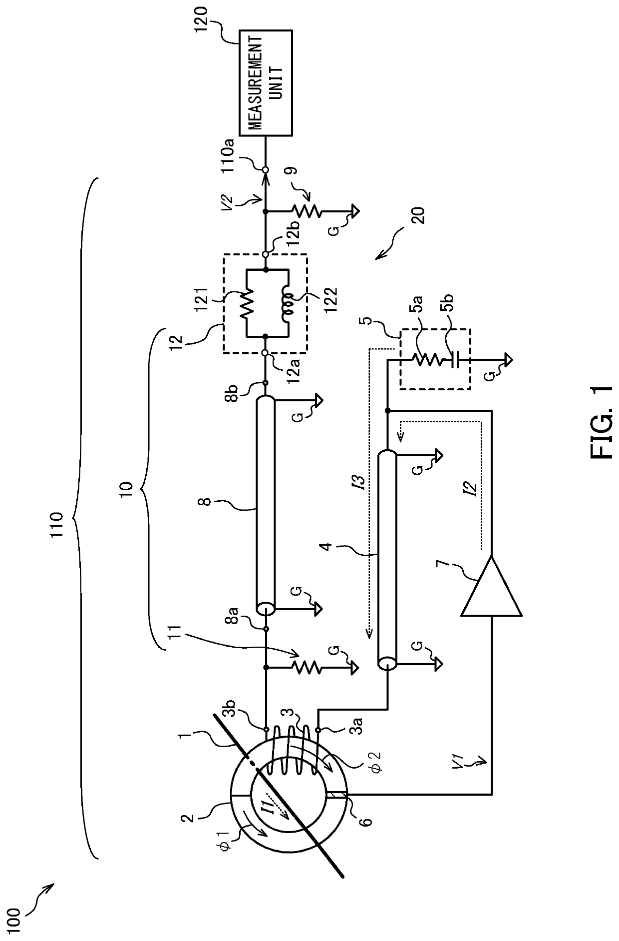
[0022]FIG. 1 is a diagram showing a configuration of a measurement device 100 according to a first embodiment.

[0023]The measurement device 100 measures a physical quantity related to an object to be measured on the basis of a detection signal as a result of detecting electric current flowing through the object to be measured. The measurement device 100 according to the present embodiment includes a current sensor 110 and a measurement unit 120.

[0024]The current sensor 110 detects electric current flowing through a measurement cable way 1 serving as the object to be measured. The current sensor 110 according to the present embodiment is configured as a zero-flux (magnetic balance) current sensor, and detects electric current to be measured I1 that is alternating current (AC) flowing through the measurement cable way 1.

[0025]The current sensor 110 includes a magnetic core 2, a coil 3, a transmission line 4, a capacitive load 5, a magnetoelectric conversion output unit 6, a voltage cur...

second embodiment

[0141]In the example described in the first embodiment, the matching circuit 12 is connected in series with the terminating end 8b of the transmission line 8. In addition to or instead of this configuration, the matching circuit 12 may be connected to the starting end 8a side of the transmission line 8. Thus, the configuration with the matching circuit 12 connected to the starting end 8a side of the transmission line 8 will be briefly described as a second embodiment with reference to FIG. 9.

[0142]FIG. 9 is a diagram showing a configuration of a measurement device 101 including a current sensor 111 according to the second embodiment. In the figure, the transmission line 4, the capacitive load 5, the magnetoelectric conversion output unit 6, and the voltage current converter 7 are omitted for the sake of illustration.

[0143]The matching circuit 12 according to the present embodiment is the same as the configuration shown in FIG. 1, but is connected to a position different from that sh...


PUM


Abstract

Technology includes a current sensor that detects electric current flowing through an object. The current sensor includes a magnetic core through which the object is inserted, a coil wound around the magnetic core, a transmission line that transmits electric current supplied from the coil, a terminating resistor that converts electric current from a terminating end of the transmission line into voltage and outputs the voltage, and an impedance matching unit that implements impedance matching between the coil and the terminating resistor. The impedance matching unit raises, to a characteristic impedance of the transmission line, at least one of an impedance viewed from the terminating end of the transmission line toward the terminating resistor and an impedance viewed from a starting end of the transmission line toward the coil, in a band of frequency components involving amplitude attenuation among frequency components of the voltage output from the terminating resistor.

Description

CROSS-REFERENCE TO RELATED APPLICATION[0001]The present application claims priority 35 U.S.C. § 119 to Japanese Patent Publication No. JP 2019-045106 (filed on Mar. 12, 2019), which is hereby incorporated by reference in its entirety.TECHNICAL FIELD[0002]The present invention relates to a current sensor and a measurement device configured to detect electric current flowing through an object to be measured.BACKGROUND ART[0003]JP2016-114585A discloses a current sensor including: a coil wound around a magnetic core through which an object to be measured is inserted; a filter that limits a frequency region of electric current input from the coil, and outputs the resultant electric current to a starting end of a transmission line; and a terminating resistor that converts the electric current from the terminating end of the transmission line to voltage.SUMMARY OF INVENTION[0004]In the current sensor described above, it is a common practice to provide a starting resistor or a terminating r...

Claims


Application Information

Patent Timeline
Patent Type & Authority Patents(United States)
IPC IPC(8): H03H7/38H03H7/01G01R15/12G01R15/18H03H7/06G01R19/00
CPCH03H7/38G01R15/183G01R19/0092H03H7/0153H03H7/06G01R15/185
Inventor TOYA, SHOGOMASUDA, HIDEKAZUYOKOTA, OSAMU
Owner HIOKI DENKI KK
Why Eureka
Try Eureka