

X-ray fluoroscopic imaging apparatus
a fluoroscopic imaging and x-ray technology, applied in the direction of instruments, angiography, patient positioning for diagnostics, etc., can solve the problems of deteriorating stitching accuracy of long images, and achieve the effect of long image and high stitching accuracy
- Summary
- Abstract
- Description
- Claims
- Application Information
AI Technical Summary
Benefits of technology
Problems solved by technology
Method used
Image

Examples
first embodiment
[0029]With reference to FIG. 1 to FIG. 8, the configuration of the X-ray fluoroscopic imaging apparatus 100 according to this embodiment will be described.
(Configuration of X-Ray Fluoroscopic Imaging Apparatus)
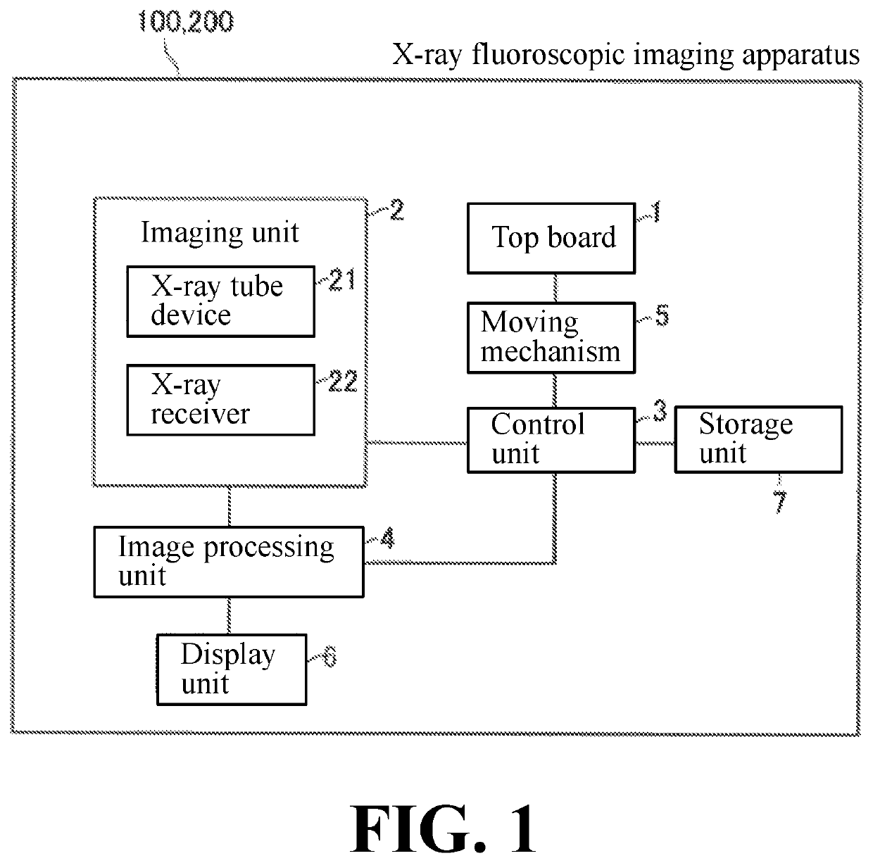
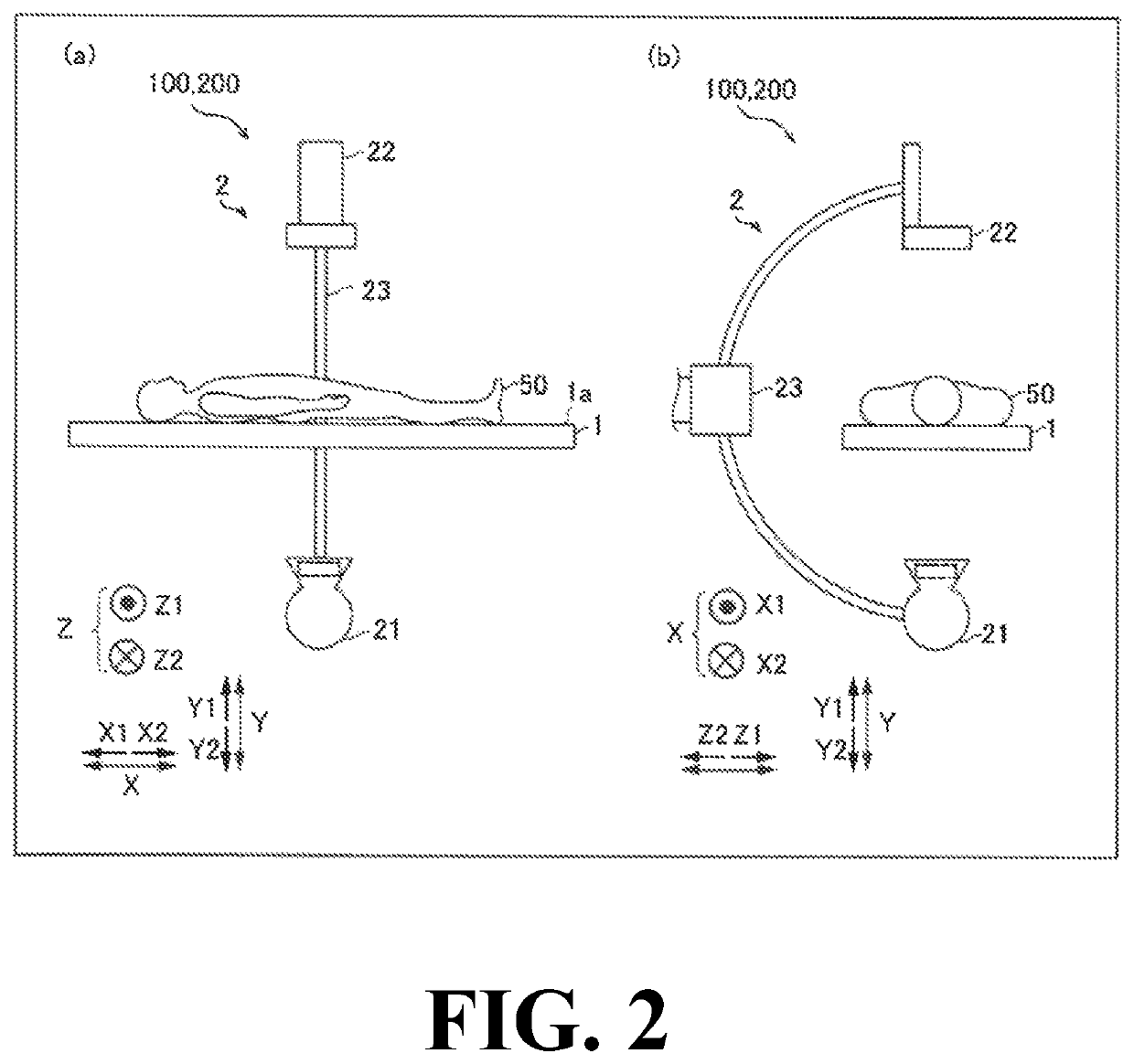
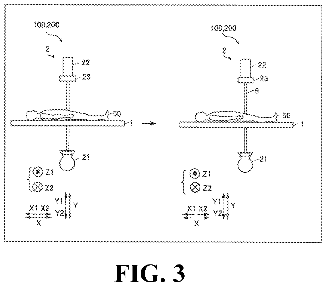
[0030]As shown in FIG. 1, (a) of FIG. 2, and (b) of FIG. 2, the X-ray fluoroscopic imaging apparatus 100 of this embodiment is provided with a top board 1 for placing a subject 50 thereon, an imaging unit 2 including an X-ray tube device 21 and an X-ray receiver 22, a control unit 3, and an image processing unit 4. Note that the X-ray tube device 21 is an example of the “X-ray source” recited in claims. Also, note that the X-ray receiver 22 is an example of the “detection unit” recited in claims.
[0031]The top board 1 is formed in a rectangular flat plate shape in a plan view. The subject 50 is placed on the placing surface 1a of the top board 1 such that the head-foot direction of the subject 50 is along the direction along the long side of the rectangle and the left-right dir...
modified examples
[0068]It should be noted that the embodiment disclosed herein is to be considered in all respects as illustrative and not restrictive. The scope of the present invention is indicated by claims rather than by the aforementioned description of the embodiment, and the scope of the present invention includes all modifications (changes) within the meaning and scope equivalent to claims.
First Modified Example
[0069]In a first modified example, the X-ray fluoroscopic imaging apparatus 100 is configured such that the control unit 3 performs control for acquiring the height information 43 (third height information) from tomographic images 40 of a blood vessel 11 or images of a blood vessel 11 captured at different angles. When acquiring X-ray images 30 for generating a long image, the subject 50 is irradiated with X-rays in the Y-direction. The images captured at different angles denote X-ray images 30 captured by emitting X-rays in a direction different from the Y-direction such as the Z-dir...
first modified example
Effects of First Modified Example
[0078]In this embodiment, as described above, the X-ray fluoroscopic imaging apparatus 200 includes the top board 1 configured to place a subject 50 thereon, the imaging unit 2 including the X-ray tube device 21 configured to irradiate the blood vessel 11 in the subject 50 placed on the top board 1 with X-rays and the X-ray receiver 22 configured to detect X-rays emitted from the X-ray tube device 21 and transmitted through the subject 50 and configured to capture a plurality of X-ray images 30 of the subject 50 while changing the relative position with respect to the top board 1, the control unit 3 configured to perform control for acquiring the plurality of pieces of height information 43 regarding the height of the blood vessel 11 from the top board 1 corresponding to the plurality of positions in a surface of the top board 1, and the image processing unit 4 configured to correct the magnification of the X-ray image 30 based on the plurality of po...
PUM
 Abstract
Description
Claims
Application Information