Temperature regulation system and temperature regulation method for machine tool

a technology of temperature regulation system and machine tool, which is applied in the direction of computer control, program control, instruments, etc., can solve the problems of reduced precision, inability to predict nonlinear structure effectively, and inability to cool or heat conventional machine tools in time, so as to improve thermal compensation precision and accuracy, reduce or eliminate thermal deformation of nonlinear structure, and high temperature response function

Active Publication Date: 2021-07-06
IND TECH RES INST
View PDF18 Cites 0 Cited by
  • Summary
  • Abstract
  • Description
  • Claims
  • Application Information

AI Technical Summary

Benefits of technology

[0007]In the temperature regulation system and the temperature regulation method according to the present disclosure, the cooling fluid storage tank and the heating fluid storage tank provide a high temperature response function, and the computing unit controls the first valve, the second valve and the third valve to switch flow directions of a plurality of the flow channels among the cooling fluid storage tank, the heating fluid storage tank and the machine tool. Therefore, a thermal balance of the machine tool is maintained, the thermal deformation of a nonlinear structure is reduced or eliminated, and the thermal compensation precision and accuracy are improved.

Problems solved by technology

A conventional working machine tool will be thermally deformed due to the heat generated by its driving components, the heat generated during cutting, or even the temperature of the working environment, and thus have reduced precision.
Therefore, the conventional machine tool cannot be cooled or heated in time.
Moreover, the conventional machine tool is compensated thermally based on experiment results of linear regression, which, however, cannot predict a non-linear structure effectively, such as an asymmetrical primary axis head structure.
As a result, the conventional machine tool suffers a poor thermal balance and has reduced precision.
Therefore, how to provide a temperature regulation system and a temperature regulation method that can solve the problems of the prior art is becoming an urgent issue in the art.

Method used


Image

  • Temperature regulation system and temperature regulation method for machine tool
  • Temperature regulation system and temperature regulation method for machine tool
  • Temperature regulation system and temperature regulation method for machine tool

Examples


Embodiment Construction

[0012]In the following detailed description, for purposes of explanation, numerous specific details are set forth in order to provide a thorough understanding of the disclosed embodiments. It will be apparent, however, that one or more embodiments may be practiced without these specific details. In other instances, well-known structures and devices are schematically shown in order to simplify the drawing.

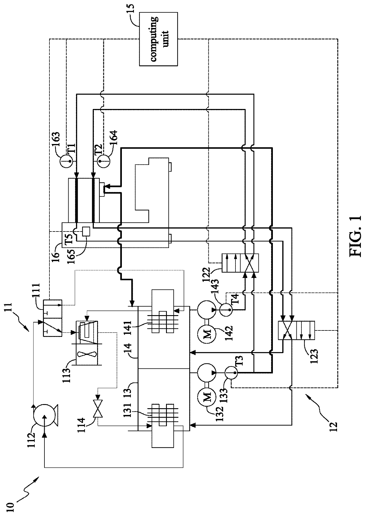
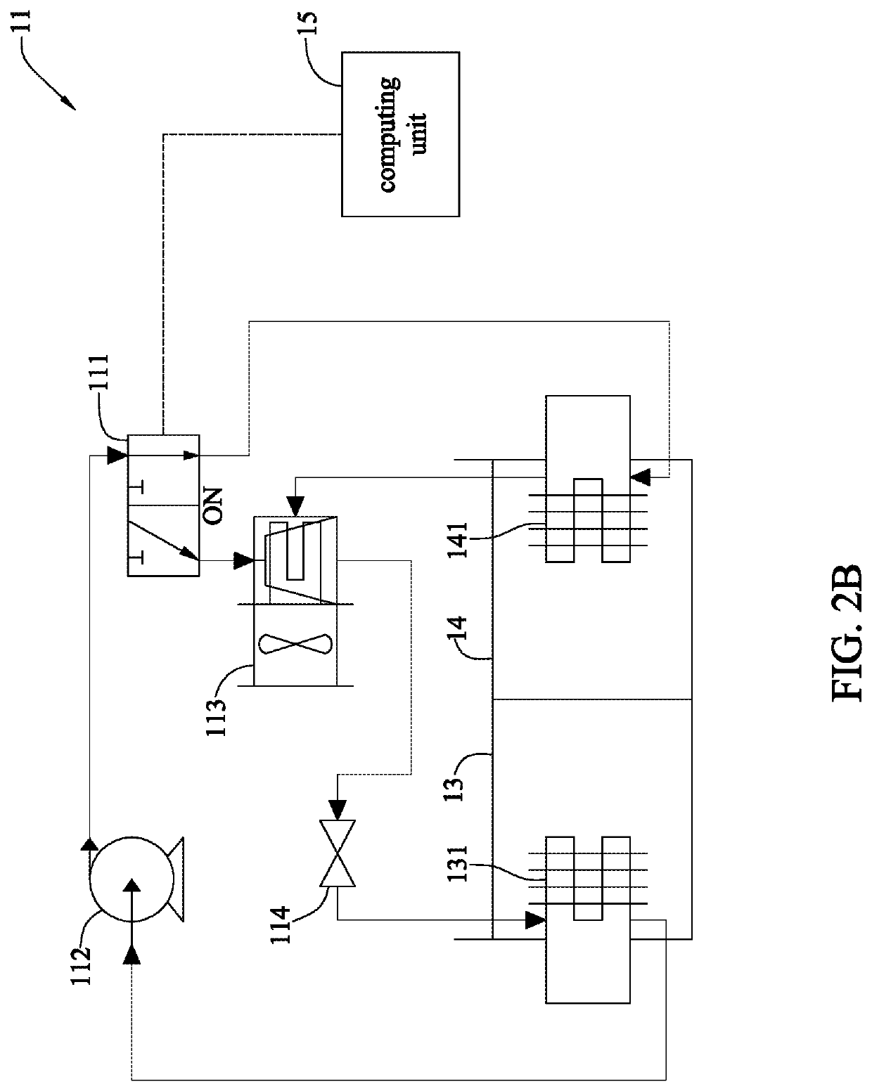
[0013]FIG. 1 schematically illustrates a temperature regulation system 10 according to the present disclosure. The temperature regulation system 10 is applied in a machine tool 16. The temperature regulation system 10 comprises a cooling fluid storage tank 13, a heating fluid storage tank 14, an internal circulation subsystem 11 (detailed in FIGS. 2A and 2B), an external circulation subsystem 12 (detailed in FIGS. 3A to 3D), and a computing unit 15. In the cooling fluid storage tank 13, a fluid (e.g., oil) is stored and a heat exchanger 131 is disposed. In the heating fluid storage ...


PUM


Abstract

A temperature regulation system and a temperature regulation method are applicable to a machine tool. The temperature regulation system includes a cooling fluid storage tank, a heating fluid storage tank, an internal circulation subsystem, an external circulation subsystem and a computing unit. The internal circulation subsystem includes a first valve. The external circulation subsystem includes a plurality of flow channels and a second valve and a third valve disposed on the plurality of the flow channels. The computing unit controls the first valve, the second valve and the third valve to switch flow directions of the plurality of the flow channels among the cooling fluid storage tank, the heating fluid storage tank and machine tool. Therefore, a thermal balance of the machine tool can be effectively maintained.

Description

BACKGROUND1. Technical Field[0001]The present disclosure relates to temperature regulation systems and temperature regulation methods, and, more particularly, to a temperature regulation system and a temperature regulation method that can heat and cool a machine tool.2. Description of Related Art[0002]A conventional working machine tool will be thermally deformed due to the heat generated by its driving components, the heat generated during cutting, or even the temperature of the working environment, and thus have reduced precision. The thermal deformation accounts for 70% of overall errors. Therefore, the conventional machine tool is equipped with a cooling machine to cool the driving components or the machine tool itself.[0003]However, the conventional cooling machine is generally equipped with only one fluid storage tank to perform cooling cycle of a fluid, and a heating rod is used to compensate the precision of the output temperature. Therefore, the conventional machine tool ca...

Claims


Application Information

Patent Timeline
Patent Type & Authority Patents(United States)
IPC IPC(8): B23Q11/14G05B15/02B23Q11/00
CPCB23Q11/141B23Q11/0003G05B15/02G05B19/404G05B2219/49215G05B2219/49219G05D23/1931
Inventor LUO, SHI-JIEHSIAO, HSI-HUNGLI, KUN-YINGWEI, SHIH-JIELIAO, YAN-SINLIN, SZU-CHIAWU, YU-HSUAN
Owner IND TECH RES INST
Why Eureka
Try Eureka