Pivotal carrier assembly for a harness

a carrier and harness technology, applied in the field of harness carrier assembly, can solve the problems of affecting affecting the use of the harness for days on end, and straining the operator's body in the long run, so as to enhance the ergonomics of the harness and increase the freedom of movemen

Active Publication Date: 2021-07-13
GLOBE (JIANGSU) CO LTD
View PDF54 Cites 0 Cited by
  • Summary
  • Abstract
  • Description
  • Claims
  • Application Information

AI Technical Summary

Benefits of technology

[0006]An object of the present invention is to provide an improved carrier assembly for a harness which allows increased freedom of movement to enhance the ergonomic properties of the harness. This object is now achieved by a carrier assembly for carrying a handheld motor-driven work tool according to a first aspect of the present invention, the carrier assembly comprising a back plate including connections for shoulder straps, a hip belt, and means for attaching the work tool, characterized in that the back plate is arranged to be connected to the hip belt by means of a pivotal connection joint to allow rotation about an axis substantially perpendicular to a plane defined by the back plate.
[0007]The carrier assembly provides a pivotal connection joint between the back plate and the hip belt giving the operator an increased degree of freedom to move whilst maintaining an optimal weight distribution of the work tool. The pivotal connection joint is arranged at the level of the hip belt, i.e. in a region of the back of the operator which naturally is more flexible and allows for increased movement in a lateral direction.
[0009]In an advantageous embodiment, the recess is arranged in a lower portion of the back plate and has an opening facing towards the tongue-shaped member on the hip belt. By providing the opening facing the tongue-shaped member of the hip belt, i.e. downwards when the back plate is in an upright position, the tongue-shaped member can be slid into the recess in a quick and easy manner, simply by moving the back plate and hip belt towards each other in a direction parallel to the plane defined by the back plate.
[0010]In an alternative embodiment, the recess further comprises a hole adapted to receive a corresponding protruding boss arranged on a resilient tab on the tongue-shaped member in a snap-fit connection, wherein the back plate is arranged to pivot about the boss on the resilient tab. Preferably, the hole in the recess has a substantially circular shape and the resilient tab has a corresponding substantially circular shape. In use when the tongue-shaped member is accommodated in the recess, the resilient tab protrudes through the hole to provide a simple but strong pivotal connection joint. The mating circular shapes of the hole and the boss provides smooth pivotal movement of the pivotal connection joint.
[0012]In an alternative embodiment, a top surface of the boss is slanted downwardly in an insertion direction of the tongue-shaped member into the recess. In other words, the top surface is angled such that the thickness of the boss tapers in the insertion direction, that is towards the end of the tongue-shaped member facing the recess in the back plate. The slanted surface facilitates smooth insertion and enables the boss on the resilient tab to spring back into locking engagement with the hole in the recess once it passes the lower rim of the hole.
[0014]In an advantageous embodiment, the tongue-shaped member is fastened to the hip belt by means of any one of welding, gluing, sewing, riveting and stapling. Preferably, the tongue-shaped member is fastened to the hip belt underneath a panel such that the pivotal connection joint is hidden from view. The fastening and placement of the tongue-shaped member on the hip belt provides a durable design and protects the pivotal connection joint.

Problems solved by technology

While this solution is sufficient for lighter equipment which is used seldom and during short periods of time, it is not adequate for professional operators who use the equipment for days on end.
As the clearing saws are usually designed for use on one side of the operator's body, the load will always be carried on one and the same shoulder, which could cause strain in the operator's body in the long run.
However, there remain some problems with an uneven load on the operator, especially when working in dense bushes or forests, where the operator is moving and has to repeatedly bend over sideways to avoid branches and twigs.
Another disadvantage with the latter type of harness is that by adjusting the shoulder straps to accommodate very tall or short operators, the comfort and weight-distributing performance of the harness is compromised.
For a tall operator, the shoulder straps may have to be maximally extended, which renders the harness more unstable, and for a short operator there is the risk that the waist belt will be placed too low on the body, which is uncomfortable, and may give a suboptimal weight distribution.
However, movement of the operator is still limited by the proposed solution in WO 2008 / 147256.

Method used


Image

  • Pivotal carrier assembly for a harness
  • Pivotal carrier assembly for a harness
  • Pivotal carrier assembly for a harness

Examples


Embodiment Construction

[0022]In the following, a detailed description of a carrier assembly according to the invention is presented. In the drawing figures, like reference numerals designate identical or corresponding elements throughout the several figures. It will be appreciated that these figures are for illustration only and are not in any way to be seen as restricting the scope of the invention.

[0023]In the context of the present invention, the terms ‘front’ and ‘rear’ shall be interpreted in relation to the operator when wearing the harness including the carrier assembly. Thus, surfaces facing in the forward direction of the operator shall be designated rear faces and surfaces facing in the opposite, backward direction of the operator shall be designated rear faces.

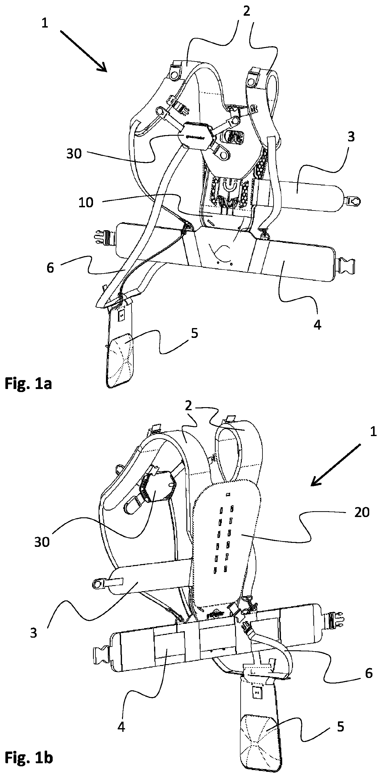
[0024]FIGS. 1a and 1b show in perspective views the front and rear of an exemplary harness 1 for carrying a handheld, motor-driven power tool (not shown) of the kind described in the introductory portion, which may be used together with a...


PUM


Abstract

A carrier assembly for a harness for carrying a handheld motor-driven work tool, the carrier assembly including a back plate having connections for shoulder straps, a hip belt, and a manner for attaching the work tool. The back plate is arranged to be connected to the hip belt by a pivotal connection joint to allow rotation about an axis substantially perpendicular to a plane defined by the back plate.

Description

TECHNICAL FIELD[0001]The present invention relates generally to a carrier assembly for a harness for carrying a hand-held motor-driven tool such as a clearing saw, the carrier assembly comprising a back plate including connections for shoulder straps, a hip belt, and means for attaching the work tool.BACKGROUND ART[0002]There is a wide variety of clearing saws and brush cutters in use in modern forestry and garden maintenance. This type of equipment is intended to be handled by one person alone, and since the equipment could be quite heavy and its vibrations and the possible counter forces, caused by the branches being cut, have to be considered, one readily realizes the need for some sort of harness to aid the operator in carrying the weight of the equipment.[0003]The simplest type of harness consists of a single band, which is worn by the operator over one shoulder and across the back and chest respectively, to support the equipment at hip level. While this solution is sufficient ...

Claims


Application Information

Patent Timeline
Patent Type & Authority Patents(United States)
IPC IPC(8): A45F3/14A45F3/10A45F5/00F16M13/04F16M13/00A45F3/00
CPCA45F3/14A45F5/00F16M13/00F16M13/04A45F3/10A45F2003/003A45F2003/142A45F2003/146A45F2200/0575A45F5/14A45F2003/122
Inventor LENNINGS, ERICEKBERG, EMMA
Owner GLOBE (JIANGSU) CO LTD
Why Eureka
Try Eureka