Harmonic distribution radial piston hydraulic machine

Active Publication Date: 2021-07-20
POCLAIN HYDRAULICS IND
View PDF12 Cites 0 Cited by
  • Summary
  • Abstract
  • Description
  • Claims
  • Application Information

AI Technical Summary

Benefits of technology

The present invention aims to improve hydraulic machines that have radial pistons by reducing sound emissions. This is done by controlling the excitation phenomena of the machine at a fundamental frequency. By making the switchovers occur at a less uniform rate, the invention broads the range of frequencies covered by fundamental excitations. This avoids generating a fundamental frequency that is practically pure, i.e. very narrow, which lowers the sound levels of the fundamental excitation and of the harmonics generated. The harmonics that combine together are fewer in number, and in general of lower level, which makes the sound effect lower and less unpleasant. In particular, this contributes to reducing whining or strident modulations.

Problems solved by technology

Such pressure shocks generate vibration in the machine and sound emissions.
Thus, an important aspect of reducing the sound emissions consists in avoiding or at least in limiting harmonic excitation from a narrow fundamental frequency, because the whine that such a fundamental frequency and its harmonic frequencies generate is deemed to be particularly unpleasant and contributes strongly to the general impression of sound nuisance.
However, such offsets are not applicable to a hydraulic machine of the type having radial pistons, and for which the axes of the cylinders are perpendicular to the axis of the machine.
Those provisions make it possible to avoid pressure shocks on opening and closing the connections between the distribution orifices and the communication orifices, and thus to reduce the initial intensity of the sound emissions at the fundamental frequency, but they do not make it possible to reduce, per se, the harmonic excitations of such emissions from the fundamental frequency.

Method used


Image

  • Harmonic distribution radial piston hydraulic machine
  • Harmonic distribution radial piston hydraulic machine
  • Harmonic distribution radial piston hydraulic machine

Examples


Embodiment Construction

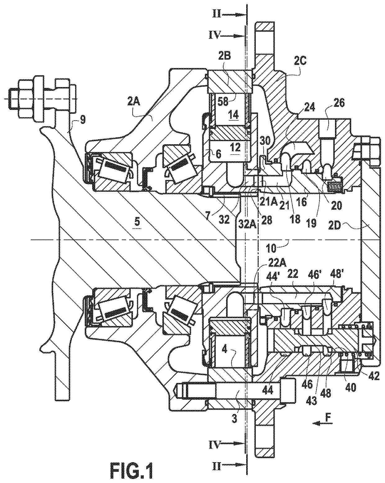
[0086]FIG. 1 shows a hydraulic machine, motor, or pump, comprising a stationary casing in three portions 2A, 2B, and 2C, assembled together by bolts 3.

[0087]Naturally, the invention is not limited to hydraulic machines having stationary casings, but rather it is also applicable to hydraulic machines having rotary casings and that are well known to the person skilled in the art.

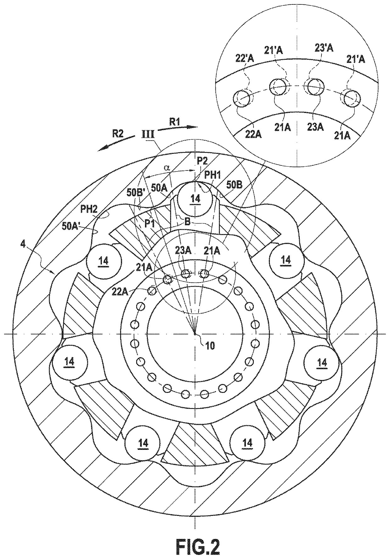
[0088]The portion 2C of the casing is closed axially by a radial plate 2D that is also fastened by bolts. An undulating reaction cam 4 is formed on the portion 2B of the casing.

[0089]The machine further comprises a cylinder block 6 that is mounted to rotate about an axis 10 relative to the cam 4, and that has a plurality of radial cylinders 12 suitable for being fed with fluid under pressure, and inside which the radial pistons 14 are mounted to slide. The cylinder block is thus the rotor of the machine.

[0090]The cylinder block 6 rotates a shaft 5, which co-operates with it via fluting 7. This shaft carries an...


PUM


Abstract

The hydraulic machine includes a cam and a cylinder block with pistons co-operating with cam lobes, each of which has two ramps extending between top and bottom dead center arcs. The cylinders are connected in alternation to a feed and to a discharge, in sequences separated by switchover stages including an isolation stage during which they are isolated relative to the feed and discharge main ducts. The angular position of the start or of the end of at least one first isolation stage relative to the corresponding dead center arc is different from the angular position of the start or of the end of at least one second isolation stage relative to its corresponding dead center arc, both of these dead center arcs being top dead center arcs or both of them being bottom dead center arcs.

Description

CROSS-REFERENCE TO RELATED APPLICATIONS[0001]This application is the United States national phase of International Application No. PCT / FR2016 / 051667 filed Jul. 1, 2016, and claims priority to French Patent Application No. 1556203 filed Jul. 1, 2015, the disclosures of which are hereby incorporated in their entirety by reference.BACKGROUND OF TITLE INVENTIONField of the Invention[0002]The present invention relates to a hydraulic machine having pistons, mounted in a cylinder block, and co-operating with a cam, the cylinders in which the pistons slide being connected sequentially to a hydraulic fluid feed and to a hydraulic fluid discharge so as to cause the cylinder block and the cam to rotate relative to each other.[0003]In particular, the machine may be a hydraulic motor or a pump.Description of Related Art[0004]In this type of machine, the pressures in the cylinders undergo intense variations, at high rates. Such pressure shocks generate vibration in the machine and sound emissions...

Claims


Application Information

Patent Timeline
IPC IPC(8): F04B1/0452F03C1/047F04B1/047F04B1/1071F03C1/34F03C1/247
CPCF04B1/0452F03C1/047F03C1/0435F03C1/0472F03C1/247F04B1/047F04B1/1071
Inventor BOZIC, ANTÉTERNOY, NICOLASGOUZOU, CHRISTOPHEGONZALEZ, SÉBASTIENDJAHANCHAH, BAMDAD-SOUFI
Owner POCLAIN HYDRAULICS IND
Why Eureka
Try Eureka