Vehicle component comprising a flow guiding element

a technology of flow guiding element and vehicle, which is applied in the direction of roofs, air flow influencers, transportation and packaging, etc., can solve the problems of reducing the flow resistance of the vehicle, and increasing the noise of the vehicle. , to achieve the effect of reducing the sound emission of the vehicle and increasing the flow resistan

Active Publication Date: 2015-03-24
ALSTOM HLDG SA
View PDF10 Cites 2 Cited by
  • Summary
  • Abstract
  • Description
  • Claims
  • Application Information

AI Technical Summary

Benefits of technology

[0008]It is therefore an object of the present invention to provide a vehicle component of the type mentioned in the introduction which does not entail the disadvantages mentioned above, or at least entails them to a lesser extent, and which in particular allows a reduction in the sound emission of the vehicle in a simple way without a significant increase in the flow resistance.

Problems solved by technology

With modern rail vehicles having comparatively high rated operating speeds, the problem generally arises that considerable noise emissions take place, specifically at high speeds, at particular positions on the vehicle where the flow separates from the vehicle components arranged there.
Although the primarily described configuration with the notches in the outer skin of the wagon body makes it possible to reduce the formation of periodic vortices and the associated noise emission, by a certain increase in the turbulence in the shear layer, it nevertheless entails the disadvantage that the shear layer widens comparatively rapidly, or strongly, in the height direction of the vehicle, so that on the one hand there is a comparatively large impact area of the shear layer on following vehicle components (such as the running gear or into the following bounding wall of the running gear cutout) with the associated sound emission, which is to this extent increased.

Method used


Image

  • Vehicle component comprising a flow guiding element
  • Vehicle component comprising a flow guiding element
  • Vehicle component comprising a flow guiding element

Examples


first embodiment

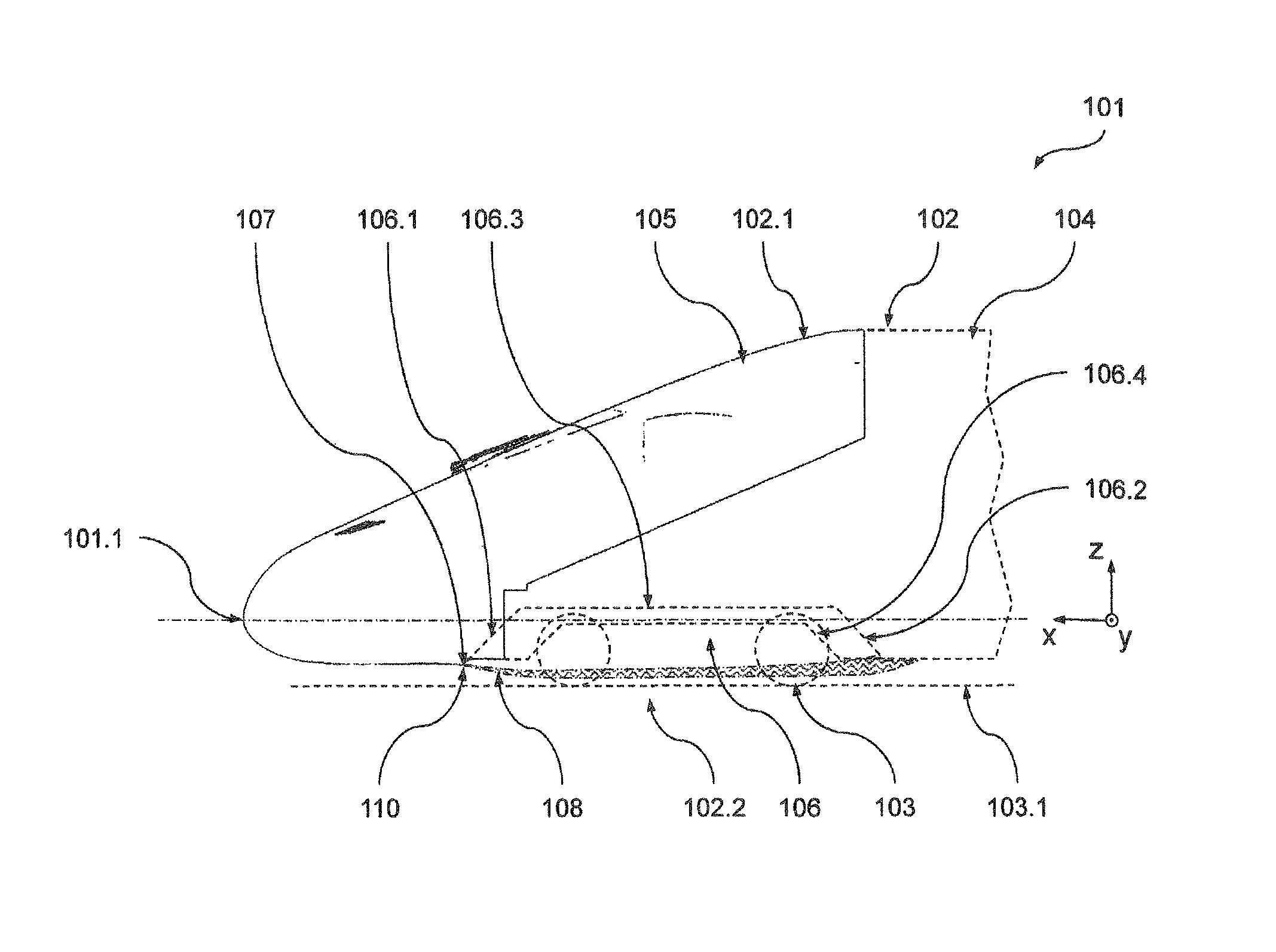
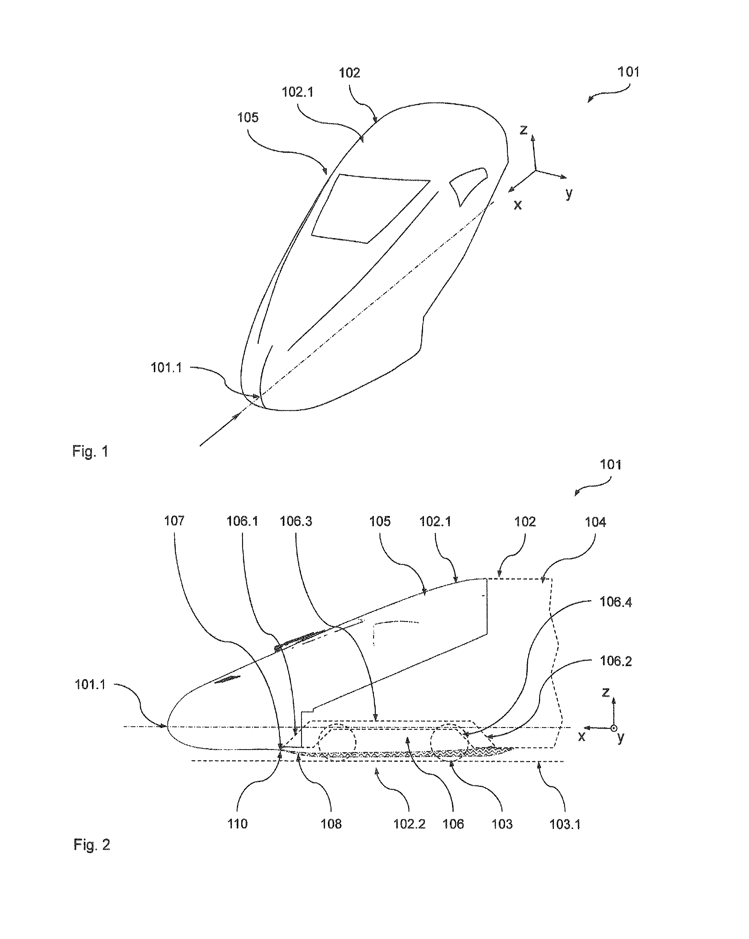
[0040]A first preferred embodiment of the vehicle according to the invention in the form of a rail vehicle 101 will be described below with reference to FIGS. 1 to 6. The rail vehicle 101 is an end carriage of a multiple-unit train for high-speed traffic, the nominal operating speed of which is more than 250 km / h, namely vn=300 km / h.

[0041]At this point, it should be noted that the following remarks are given for a flow state when driving the vehicle 101 with constant speed on a straight level track without the influences of side wind or the like, unless explicit indications are given otherwise. It is to be understood that, in the event of a departure from this operating state (for example due to negotiation of a curve, or side wind etc.), differences may arise from the flow conditions described, in particular the flow directions, although the basic statements substantially still apply.

[0042]The vehicle 101 comprises a wagon body 102, which defines an outer skin 102.1 of the vehicle ...

second embodiment

[0067]Another advantageous embodiment of the vehicle 201 according to the invention, comprising another preferred embodiment of the vehicle component according to the invention in the form of a head module 205, will be described below with reference to FIGS. 1 to 3, 7 and 8. The vehicle 201 corresponds in its basic configuration and functionality to the vehicle 101 of FIGS. 1 to 6, so that only the differences will be discussed here. In particular, components which are of the same type are provided with references increased by the value 100. Unless otherwise mentioned below, with respect to the features, functions and advantages of these components reference is made to the comments above relating to the first embodiment.

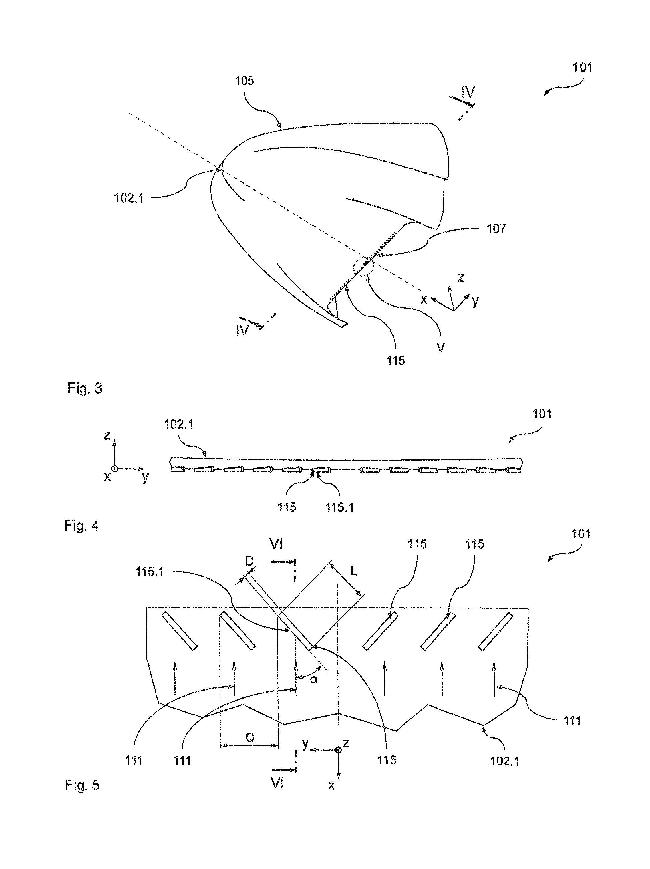
[0068]FIG. 7 shows a section through the head module 205, which corresponds to the section of FIG. 6, while FIG. 8 shows a view which corresponds to the view of FIG. 5. The only difference from the embodiment of FIGS. 1 to 6 is that the guide face 215.1 is formed by ...

third embodiment

[0072]Another advantageous embodiment of the vehicle component according to the invention, in the form of a pantograph 316 of the vehicle 101, will be described below with reference to FIGS. 1 to 3, 9 and 10. With respect to their basic configuration, arrangement and functionality, the perturbing elements 315 of the pantograph 316 correspond to the perturbing elements 115 of FIGS. 1 to 6, so that only the differences will be discussed here. In particular, components which are the same type are provided with references increased by the value 200. Unless otherwise mentioned below, with respect to the features, functions and advantages of these components reference is made to the comments above relating to the first embodiment.

[0073]One difference is that the perturbing elements, or turbulator elements, are arranged on the lower side of a contact device 316.1 of the pantograph 316. More precisely, the turbulator elements 315 are arranged on the lower side of a carrier 316.2 which carri...


PUM


Abstract

A vehicle component includes a surface which, during operation, is exposed to an air flow. The surface includes a separating area where the air flow separates from the surface, and at least one obstructing element associated with the separating area for introducing an obstruction into the air flow. The obstructing element includes at least one guide surface which protrudes into the air flow. The guide surface is inclined relative to the local direction of the main air flow so that it confers on the part of the main air flow that impacts the guide surface a speed component that runs perpendicular to the local direction of the main air flow and induces turbulence in the air flow downstream of the obstructing element.

Description

BACKGROUND OF THE INVENTION[0001]1.Field of the Invention[0002]The present invention relates to a vehicle component for a vehicle, in particular a rail vehicle for high-speed traffic, comprising a surface which, during operation, is exposed to a relative wind-induced air flow having a local main flow direction, wherein the surface has a separation region in which the air flow separates from the surface, and at least one perturbing element associated to the separation region is provided, which is formed in order to introduce a perturbation into the air flow. The invention furthermore relates to a vehicle comprising such a vehicle component.[0003]2.Description of Related Art.[0004]With modern rail vehicles having comparatively high rated operating speeds, the problem generally arises that considerable noise emissions take place, specifically at high speeds, at particular positions on the vehicle where the flow separates from the vehicle components arranged there. This is due, inter al...

Claims


Application Information

Patent Timeline
Patent Type & Authority Patents(United States)
IPC IPC(8): B62D35/00B60L5/20B61D17/02
CPCB61D17/02B60L5/20Y02T30/32B60L2200/26Y02T30/00
Inventor ORELLANO, ALEXANDERSCHOBER, MARTINTIETZE, ANDREASBLASCHKO, RENE
Owner ALSTOM HLDG SA
Why Eureka
Try Eureka