Comminution device for laboratory operation, and damper for a comminution device

a comminution device and laboratory technology, applied in the direction of grain treatment, etc., can solve the problems of vibration emissions, vibration radiation, and vibration effects, and achieve the effects of reducing sound radiation, reducing sound emissions, and simple and inexpensive manner

Active Publication Date: 2021-04-13
RETSCH GMBH & CO KG
View PDF21 Cites 0 Cited by
  • Summary
  • Abstract
  • Description
  • Claims
  • Application Information

AI Technical Summary

Benefits of technology

[0007]The object of the present invention is to provide a comminution device of the type mentioned that has a greatly reduced sound radiation in the comminution and milling operation. The invention in particular is based on the object of reducing sound emissions that emerge as noise through the milling material channel or are transmitted through the housing and / or device parts of the comminution device forming the milling material channel and / or adjoining them in a simple and inexpensive manner in terms of equipment, wherein, preferably, supplying a milling material to the milling chamber and if necessary removing a milling material from the milling chamber are possible during the milling operation.

Problems solved by technology

These signals, coupled to the rotational speed of the comminution system, are very disturbing due to the usually high speeds in laboratories.
With centrifugal mills, this leads to strong impacts during the milling process due to high centrifugal forces acting on the parts being crushed by a fast-rotating milling tool.
Furthermore, vibration emissions occur based on shocks and vibrations of equipment parts of the comminution device directly or indirectly surrounding the milling chamber.
These equipment parts can cause ambient air to vibrate and thus amplify sound emissions from the milling material channel.
In addition, the vibrating machine parts in turn cause adjacent equipment parts to vibrate, with the result that the adjacent equipment parts also create noise.
However, a complete encapsulation of the comminution device by a soundproof enclosure is not possible if the milling material channel must be open to supply or remove milling material during the milling operation.

Method used


Image

  • Comminution device for laboratory operation, and damper for a comminution device
  • Comminution device for laboratory operation, and damper for a comminution device
  • Comminution device for laboratory operation, and damper for a comminution device

Examples


Embodiment Construction

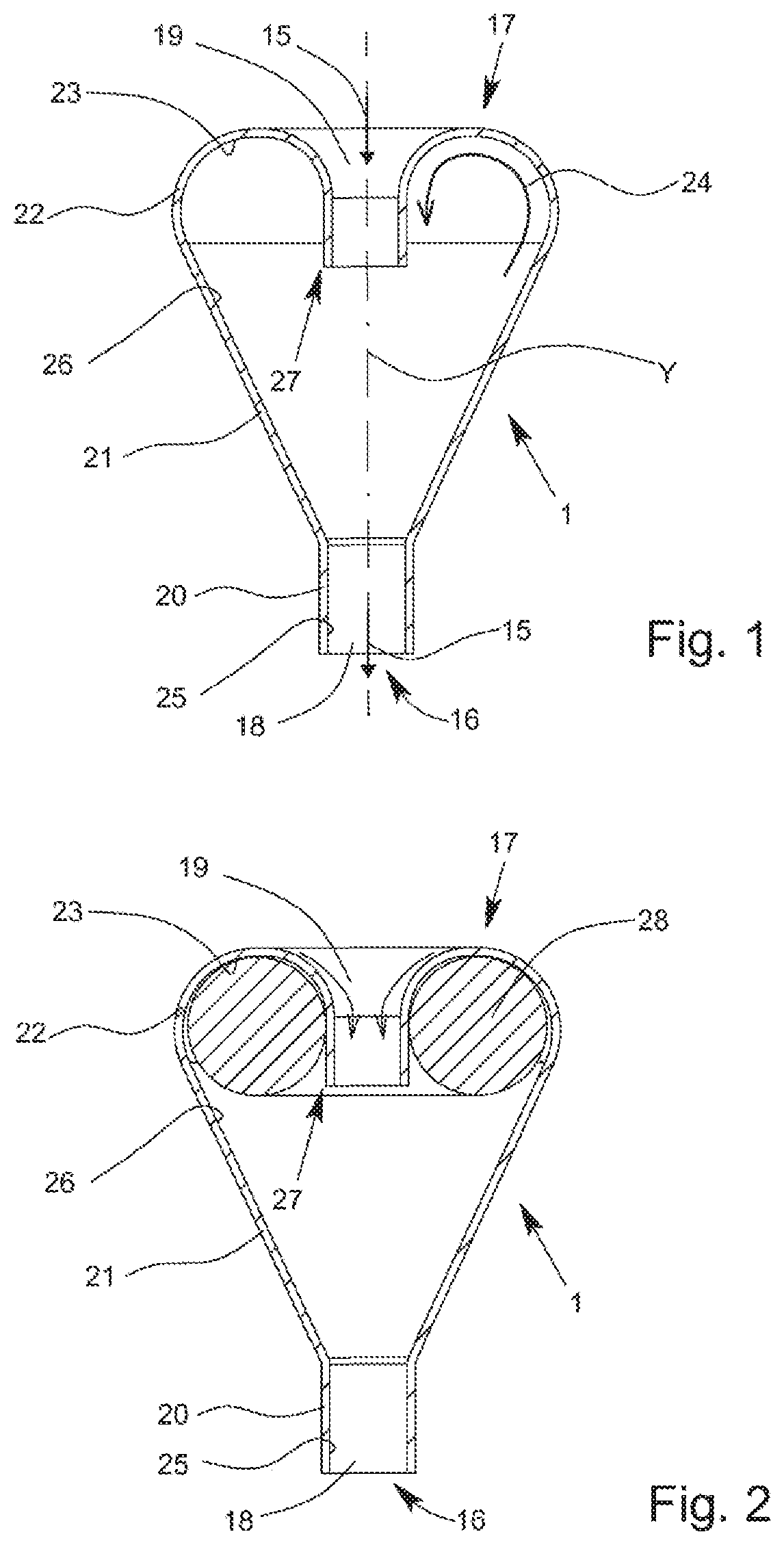
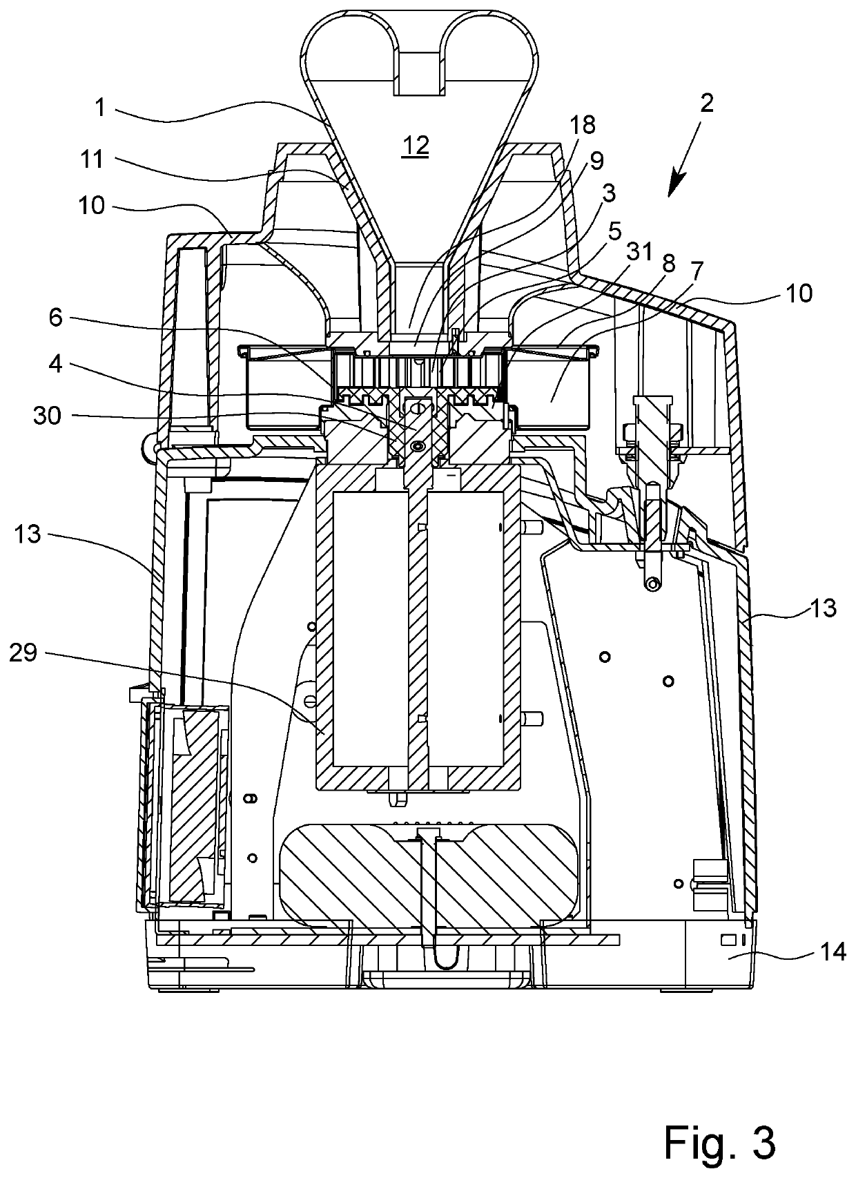
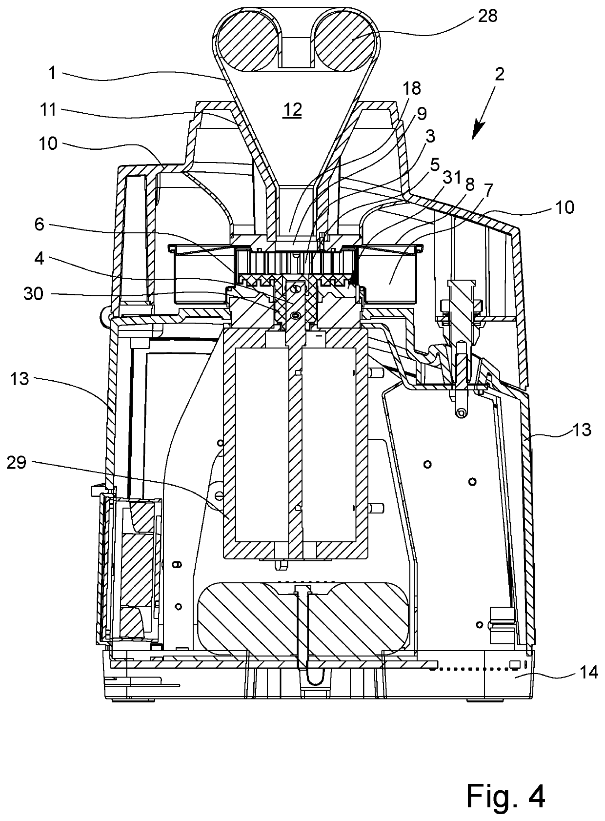
[0050]FIG. 1 shows a muffler 1 as a separate device part for use in a comminution device 2 for laboratory operation, for example as shown in FIGS. 3 and 4. The comminution device 2 is, for example, a centrifugal mill as shown. The basic structure of the comminution device 2 can correspond to the basic structure of the centrifugal mill described in EP 0 727 254 A1. The damper 1 is designed for passive reduction of noise emissions emanating from a milling chamber 3.

[0051]As shown in FIGS. 3 and 4, the comminution device 2 has a rotor 5 coupled to a drive shaft 4 as milling tool, where the milling chamber 3 of rotor 5 is surrounded by an annular sieve 6 and on the outer circumference of the annular sieve 6 an annular collection container 7 is arranged for the crushed milling material. The collection container 7 is covered with a container lid 8. The milling unit consisting of rotor 5, annular sieve 6 and collection container 7 can be closed with a housing lid 10 having a milling materi...


PUM


Abstract

A comminution device for laboratory operation is described. More specifically, a laboratory mill, particularly a centrifugal mill, is provided that includes a milling tool arranged in a milling chamber, a housing assembly, and a milling material channel running through the housing assembly. The milling material channel opens into the milling chamber and is configured to supply, for supplying milling material to the milling chamber or to discharge milled material from the milling chamber. The milling material channel may be open to the environment and/or can be opened for successively supplying milling material to the milling chamber during the milling operation. At least one system for passively reducing noise emissions is provided and situated in the region of the milling material channel.

Description

[0001]This application is the National Phase of PCT Application No. PCT / EP2017 / 025058, filed Mar. 24, 2017, which claims the benefit of German Patent Application Serial Nos. 102016003493.9 and 102016013022.9, filed with the German Patent and Trade Mark Office on Mar. 24, 2016 and Nov. 2, 2016, respectively.FIELD OF THE INVENTION[0002]The invention relates to a comminution device for laboratory operation, particularly a laboratory mill, especially particularly a centrifugal mill, with a milling tool arranged in a milling chamber, with a housing assembly and with a milling material channel running through the housing assembly into the milling chamber for supplying milling material to the milling chamber and / or discharging milling material from the milling chamber, in particular wherein the milling material channel during milling operation is open to the environment and / or can be opened, especially particularly for successively supplying a milling material to the milling chamber during...

Claims


Application Information

Patent Timeline
Patent Type & Authority Patents(United States)
IPC IPC(8): B02C18/00B02C18/22B02C23/02B02C18/06B02C23/00
CPCB02C18/2291B02C18/062B02C23/00B02C23/02
Inventor JANETTA, FRANKEISENBACH, RALFHOEHNE, ALEXANDER
Owner RETSCH GMBH & CO KG
Why Eureka
Try Eureka