Multi-stage piston compressor having an outer cooling air conduction system

A technology for cooling air and compressors, which is applied to the components of pumping devices for elastic fluids, multi-stage pumps, liquid variable displacement machines, etc., which can solve the problem of cooling air disappearing and achieve the effect of reducing sound radiation

Active Publication Date: 2017-08-29
KNORR BREMSE SYST FUR SCHIENENFAHRZEUGE GMBH
View PDF6 Cites 0 Cited by
  • Summary
  • Abstract
  • Description
  • Claims
  • Application Information

AI Technical Summary

Problems solved by technology

However, most of the cooling air of the axial fan is lost through the vortex formed due to the collision with the cylinder

Method used


Image

  • Multi-stage piston compressor having an outer cooling air conduction system
  • Multi-stage piston compressor having an outer cooling air conduction system
  • Multi-stage piston compressor having an outer cooling air conduction system

Examples


Embodiment Construction

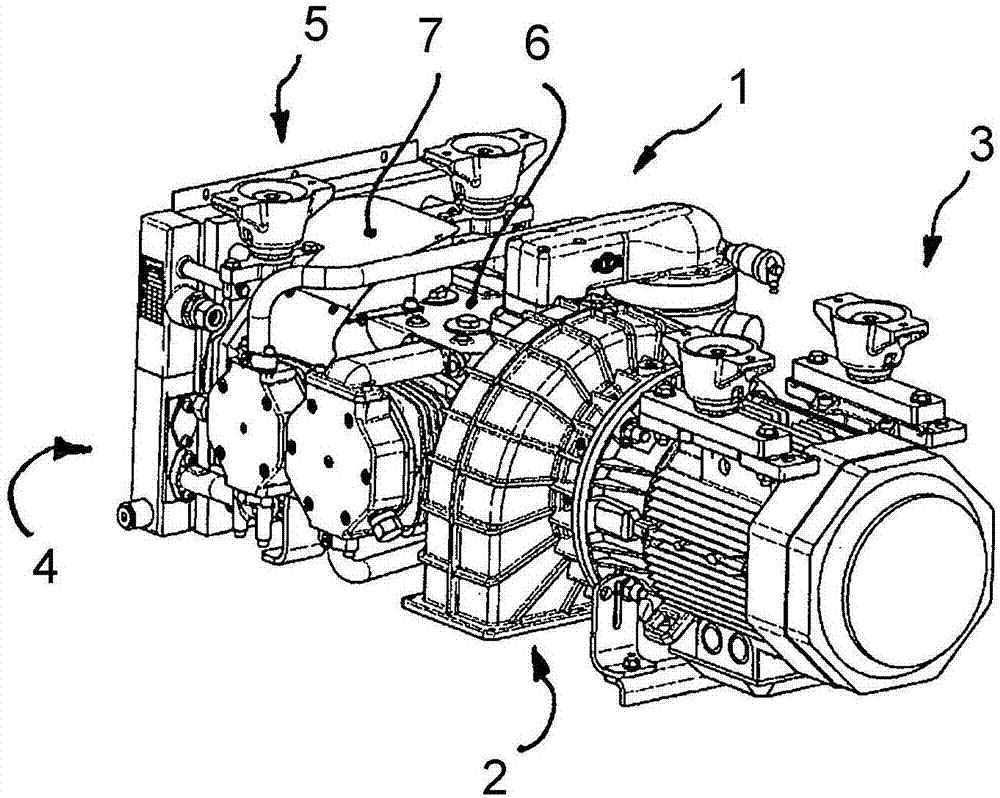
[0024] according to figure 1 , the multi-stage piston compressor mainly comprises a compressor unit 1, a motor unit 3 in the form of an electric motor is flanged to the first end side 2 of the compressor unit, and a cooler unit 5 is installed at the opposite end on side 4. The cooler unit 5 serves to cool the compressed air flow heated by the compression inside the compressor unit 1 by means of an axial fan wheel (not visible here) for generating cooling air along the compressor unit 1 1 flows externally. For external cooling air guidance in the region of the compressor unit 1 , an air guidance housing 7 extending partially radially around the crankcase 6 in an arc is provided.

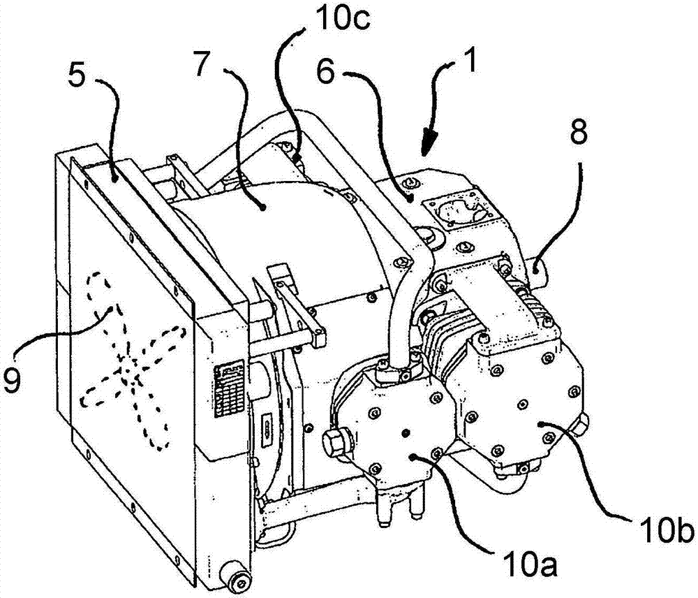
[0025] according to figure 2 , the crankshaft 8 mounted rotatably in the crankcase 6 (which can be seen here with the motor unit disassembled) drives the axial flow of the cooler unit 5 , shown schematically by shaded outline. Fan impeller 9. The axial fan impeller 9 generates an air flow along ...


PUM


Abstract

The invention relates to a multi-stage piston compressor which comprises a compressor unit (1) having a plurality of air-cooled cylinders (10a-10c), the crankshaft (8) of said compressor unit being housed in a crankcase (6) and driving a motor unit (3) that is flange-mounted on an end face (2) on said compressor. On the opposing end face (4) of the compressor unit (1), a cooler unit (5) is arranged, mounted on said compressor unit and driven by the crankshaft (8), the integrated axial fan wheel (9) of said cooler unit blowing the generated cooling air substantially outwards along the compressor unit (1) and, in order to conduct cooling air externally in the region of said compressor unit (1), at least one air guide housing (7) which extends at least partially radially around the crankcase (6) in a curved manner being mounted on said cooler unit (5) on the air inlet side and being mounted on the compressor unit (1) crankcase (6) on the air outlet side such that the axial air flow which is generated by said axial fan wheel (9) is at least partially taken in by the air guide housing (7) and at least partially guided around the crankcase (6) in the radial direction so as to reach at least one cylinder (10a) arranged on the air outlet side of said air guide housing (7).

Description

technical field [0001] The invention relates to a multi-stage piston compressor having a compressor unit comprising a plurality of air-cooled cylinders, the crankshaft of which is mounted in a crankcase and is mounted on the compressor unit Driven on one end side by means of a flanged motor unit, wherein a cooler unit driven by the crankshaft and mounted on the compressor unit is arranged on the opposite end side of the compressor unit, the cooler unit The unit's integrated axial fan impeller blows the resulting cooling air substantially outwards along the compressor unit. Furthermore, the invention also relates to a rail vehicle having a compressed air system, in particular a pneumatic braking system, which comprises a multistage piston compressor of this type for generating compressed air. Background technique [0002] The field of application of the invention extends primarily to rail vehicle design. Increased environmental requirements with regard to emissions of harmf...

Claims


Application Information

Patent Timeline
Patent Type & Authority Applications(China)
IPC IPC(8): F04B25/00F04B27/00F04B27/02F04B39/06F04B53/08
CPCF04B25/005F04B27/005F04B27/02F04B39/064F04B39/066F04B53/08F04B53/002
Inventor M·伯克M·弗里茨S·弗罗里希A·莱伯芬格
Owner KNORR BREMSE SYST FUR SCHIENENFAHRZEUGE GMBH
Why Eureka
Try Eureka