Exhaust component of gas exhaust line

a technology of exhaust gas and component, which is applied in the direction of exhaust treatment, engine components, mechanical equipment, etc., can solve the problems of exhaust line dysfunction and deformation of movable means, and achieve the effects of reducing the temperature of exhaust gases, reducing counter-pressure, and less energy

Active Publication Date: 2009-06-11
FAURECIA SYST DECHAPPEMENT
View PDF12 Cites 2 Cited by
  • Summary
  • Abstract
  • Description
  • Claims
  • Application Information

AI Technical Summary

Benefits of technology

[0020]The advantages of the present invention consist in that the exhaust-line element includes a three-way valve installed downstream with respect to the parallel exhaust tubes, thus after a silencer or a decontamination element. Such an installation advantageously allows lowering the temperature of the exhaust gases penetrating into this three-way valve.
[0021]Another advantage consists in that the first exhaust tube includes an exhaust component, whereas the second exhaust tube includes a silencer, which advantageously allows reducing the counter-pressure in the first exhaust tube and thus to use means for activating the valve that consume less energy and, especially, having a reduced size compared to the state-of-the-art valves.
[0022]Still another advantage resides in that the first exhaust tube includes a decontamination element, whereas the second exhaust tube includes a silencer. Therefore, when the three-way valve ensures the closing of the first exhaust tube, the exhaust gases pass through the silencer and the acoustic behavior of the exhaust line is at its maximum efficiency. When this three-way valve ensures the closing of the second exhaust tube, the exhaust gases pass through said decontamination element, which also has a sound-attenuation effect that can be very slightly lower than that produced by the silencer of the second exhaust tube. Thus, irrespective the tube through which exhaust gases pass, a clear reduction of the sound emission at the level of the exhaust line undoubtedly occurs, in contrast to the state-of-the-art devices.

Problems solved by technology

Because of the installation of the three-way valve near the engine, the exhaust gases, coming from this engine and having a particularly high temperature, subject this three-way valve to such temperature stresses that they cause degradations to the movable means, which results into a dysfunction of the exhaust line.

Method used


Image

  • Exhaust component of gas exhaust line
  • Exhaust component of gas exhaust line

Examples


Embodiment Construction

[0027]The invention relates to the field of the car industry and, in particular, to that of the manufacture of equipment to ensure the exhaust of gases resulting from the combustion of a fuel within a thermal combustion engine a motor vehicle includes.

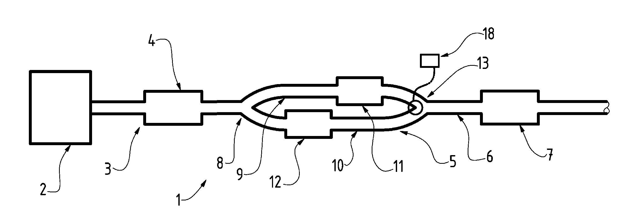
[0028]As can be seen in FIG. 1, such equipment of the present invention is in the form of an exhaust line 1 for these gases connected to the engine 2 of such a motor vehicle.

[0029]This exhaust line 1 includes, in the direction of the flow of the gases resulting from the combustion of the fuel within this engine 2:[0030]an upstream pipe 3 being connected to that engine 2 and including a light-off catalyst 4 or the like;[0031]an exhaust component 5 connected to said upstream pipe 3; and[0032]a downstream pipe 6 being connected to said exhaust component 5 and including a main-type silencer 7.

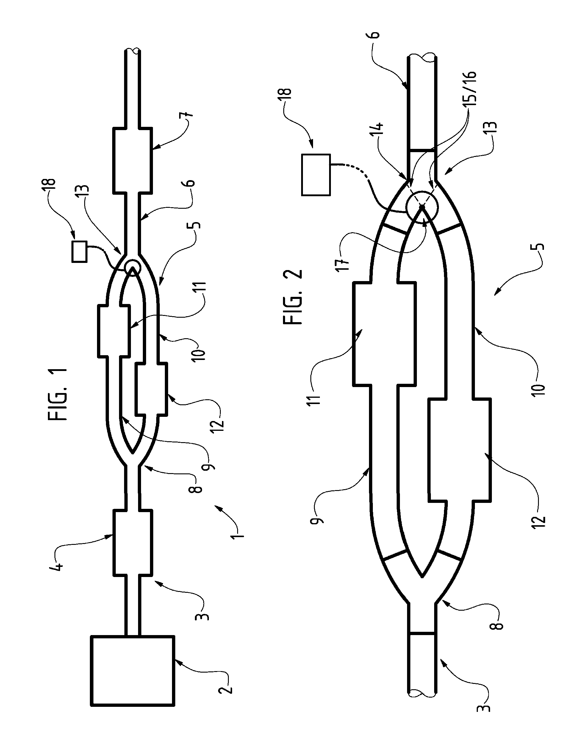
[0033]As regards said exhaust component 5 shown in more detail in FIG. 2, the component 5 includes, here too in the direction of the gas flow:[0034]a...


PUM


Abstract

The invention relates to an exhaust component in a gas exhaust line for gases produced by the combustion of a fuel in a heat engine. In the gas flow direction, there is a first connection to an upstream pipe carrying gases from the engine. There is also a first exhaust tube and a second exhaust tube, these two tubes being parallel and being connected to the first connection. There is a second connection to a downstream gas discharge pipe, connected to the parallel exhaust tubes. The component is characterized in that, firstly the first tube has a depolluting component, and the second tube has a silencer. The second connection is a three-way valve.

Description

CROSS-REFERENCE TO RELATED U.S. APPLICATIONS[0001]Not applicable.STATEMENT REGARDING FEDERALLY SPONSORED RESEARCH OR DEVELOPMENT[0002]Not applicable.Names of Parties to a Joint Research Agreement[0003]Not applicable.REFERENCE TO AN APPENDIX SUBMITTED ON COMPACT DISC[0004]Not applicable.BACKGROUND OF THE INVENTION[0005]1. Field of the Invention[0006]The present invention relates to an exhaust component, which is included in a gas-exhaust line for gases resulting from the combustion of a fuel within a heat engine. This invention also relates to an exhaust line including such an exhaust component as well as to an installation for the exhaust of gases including such an exhaust component.[0007]This invention relates to the field of the car industry and, in particular, to that of the manufacture of equipment to ensure the exhaust of gases resulting from the combustion of a fuel within a thermal combustion engine, which a motor vehicle includes.[0008]2. Description of Related Art[0009]Incl...

Claims


Application Information

Patent Timeline
Patent Type & Authority Applications(United States)
IPC IPC(8): F01N3/28F01N13/08
CPCF01N1/16F01N3/0878F01N2230/04F01N13/011F01N2410/00Y02T10/20F01N2240/18Y02T10/12
Inventor DEVISMES, STEPHANE
Owner FAURECIA SYST DECHAPPEMENT
Why Eureka
Try Eureka