
Self-wringing foam cotton mop with labor-saving wringing operation

a foam cotton mop and labor-saving technology, applied in the field of foam cotton mops, can solve the problems of high cost of wringing frames, inability to completely separate collodion heads, and increased friction during wringing operations, so as to achieve labor-saving operation, short contact distance, and small resistance during wringing operations

Active Publication Date: 2021-07-27
NINGBO DERUNTANG INTELLIGENT TECH CO LTD
View PDF10 Cites 0 Cited by
  • Summary
  • Abstract
  • Description
  • Claims
  • Application Information

AI Technical Summary

Benefits of technology

The solution provides a labor-saving wringing operation with reduced friction and material contact, allowing for efficient cleaning and easier storage, as the mop can be placed vertically for drying, enhancing usability and reducing transportation costs.

Problems solved by technology

Firstly, in this wringing approach, the wringing operation is performed by moving the wringing frame in a height direction of the collodion mop.
In addition, there generally are multiple rows of wringing bars on a front side or a rear side, the material consumption is large, and the contact area of the wringing bars with the collodion head is very large during the wringing process, so that the friction during the wringing operation is greatly increased and the wringing frame is high in cost.
Secondly, due to the special structure of the wringing frame, the collodion head and the mop rod must be fixedly connected to each other, and the collodion head cannot be completely separated from the wringing frame, that is, the collodion head cannot be rotated relative to the mop rod.
Thus, during the mopping process, it is inconvenient for mopping particular occasions such as a corner, and the adaptability of mopping is low.
Thirdly, since a lengthwise direction of the collodion head if perpendicular to an axial direction of the mop rod during the storage of the existing collodion mop, a very large space is required to store the collodion mop, and it is inconvenient for storing the collodion mop.
Moreover, the packing boxes for the existing collodion mops is large in size, so less collodion mops are placed in the same space, and the transportation cost is increased.
Moreover, the squeezing force gradually increases, the foam cotton head can be better dewatered, and the wringing operation is labor-saving.
Thus, it is advantageous for allowing the foam cotton head to exit from the through hole, and the wringing operation is further labor-saving.
In the schemes, the wringing approach of the existing foam cotton mops is completely overturned.
Since the squeezing mechanism comes into contact with foam cotton head only in the thickness direction, the contact distance is short, the resistance during the wringing operation is small, and the wringing operation is labor-saving.

Method used


Image

  • Self-wringing foam cotton mop with labor-saving wringing operation
  • Self-wringing foam cotton mop with labor-saving wringing operation
  • Self-wringing foam cotton mop with labor-saving wringing operation

Examples


first embodiment

[0045]As shown in FIGS. 1-8, the present invention is shown.

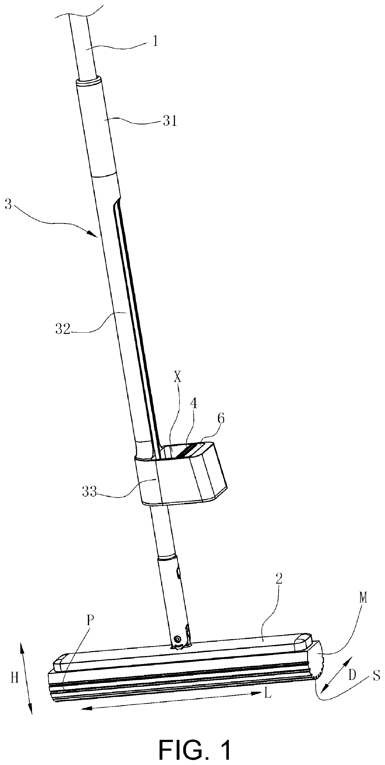
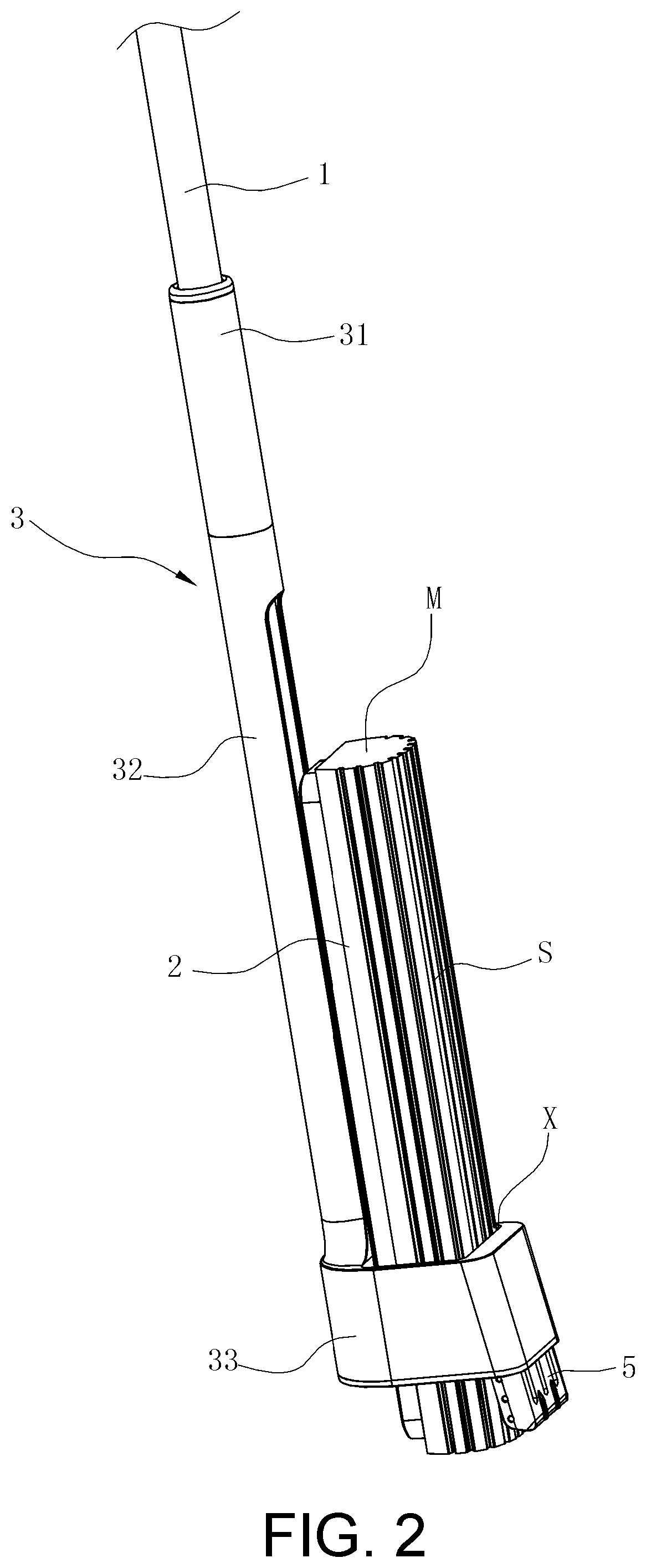
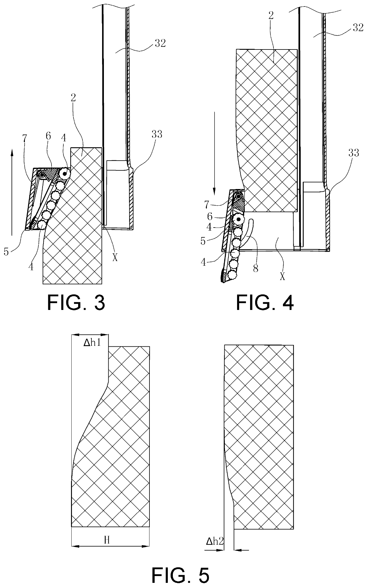
[0046]A self-wringing foam cotton mop with a labor-saving wringing operation is provided, including a mop rod 1 and a foam cotton head 2. The foam cotton head 2 is rotatably connected to a bottom end of the mop rod 1. A wringing frame 3 capable of sliding along the mop rod 1 is provided on the mop rod 1, and the wringing frame 3 has a through hole X for allowing an end face M of the foam cotton head 2 to pass therethrough. The end face M refers to surfaces of two sides of the foam cotton head 2 in a lengthwise direction L. A squeezing mechanism capable of moving (e.g., swinging) relative to the wringing frame 3 is provided on an inner front side of the through hole X, so that a position of the squeezing mechanism during an upward movement of the foam cotton head 2 relative to the wringing frame 3 is different from the position of the squeezing mechanism during a downward movement of the foam cotton head 2 relative to the wr...

second embodiment

[0056]As shown in FIGS. 9 and 10, the present invention is shown.

[0057]Differences between this embodiment and the first embodiment are as follows. The squeezing mechanism includes a squeezing plate 5. A wringing roller 4 adapted to be in contact with the bottom surface S of the foam cotton head 2 is provided on the squeezing plate 5, and a lower end of the squeezing plate 5 is hinged within the through hole X. An elastic member 7 for keeping an upper end of the squeezing plate 5 in a trend of deflecting close to the bottom surface S of the foam cotton head 2 is provided within the through hole X, and the elastic member 7 is a torsion spring. A limiting portion 9 for limiting a rotation position of the squeezing plate 5 is further provided within the through hole X. Under the combined action of the elastic member 7 and the limiting portion 9, the squeezing plate 5 is always kept in a state of gradually inclining towards the bottom surface S of the foam cotton head 2 from the bottom ...

third embodiment

[0059]As shown in FIGS. 11 and 12, the present invention is shown.

[0060]Differences between this embodiment and the first embodiment are as follows. The squeezing mechanism includes a squeezing plate 5. A wringing roller 4 for coming into contact with the bottom surface S of the foam cotton head 2 is provided on the squeezing plate 5, and a lower end of the squeezing plate 5 is hinged within the through hole X. A limiting portion 9 for limiting a rotation position of the squeezing plate 5 is provided within the through hole X, and an upper end of the squeezing plate 5 is locked within the through hole X by a locking structure that can be unlocked. In a state where an upper end of the squeezing plate 5 is locked by the locking structure, the squeezing plate 5 is kept at a position where it is gradually inclined towards the bottom surface S of the foam cotton head 2 from the bottom up.

[0061]The locking structure includes a first lock bar 9a and a second lock bar 9b which are arranged ...


PUM

PropertyMeasurementUnit
thicknessaaaaaaaaaa
structureaaaaaaaaaa
elastic forceaaaaaaaaaa

Abstract

A self-wringing foam cotton mop includes a mop rod and a foam cotton head connected to a bottom end of the mop rod. A wringing frame is disposed on the mop rod. During mopping, the foam cotton head is separated from the wringing frame. A squeezing mechanism capable is disposed on the wringing frame. The position of the squeezing mechanism when the foam cotton head is moved up relative to the wringing frame is different from the position of the squeezing mechanism when the foam cotton head is moved down relative to the wringing frame, and a first amount of deformation generated by the foam cotton head during an upward movement of the foam cotton head relative to the wringing frame is greater than the second amount of deformation generated by the foam cotton head during a downward movement of the foam cotton head relative to the wringing frame.

Description

CROSS-REFERENCE TO RELATED APPLICATION[0001]This application is a 371 of international application of PCT application serial no. PCT / CN2018 / 000203, filed on Jun. 1, 2018, which claims priority to and the benefit of China Patent Application No. 201710442151.6, filed on Jun. 13, 2017. The entirety of each of the above-mentioned patent applications is hereby incorporated by reference herein and made a part of this specification.BACKGROUNDTechnical Field[0002]The present invention relates to a foam cotton mop, and in particular to a self-wringing foam cotton mop with a labor-saving wringing operation, wherein the foam cotton can be collodion, sponge or the like.Description of Related Art[0003]Collodion mops available in the market are roughly the same in structure. Such a collodion mop includes a mop rod, a mop head and a wringing mechanism. The wringing device in the collodion mop is a transmission structure. The wringing device includes a handle, a pull rod, a caliper seat (a wringing...

Claims


Application Information

Patent Timeline
Patent Type & Authority Patents(United States)
IPC IPC(8): A47L13/144A47L13/24
CPCA47L13/144A47L13/24A47L13/146A47L13/257A47L13/16
Inventor HE, MINWU, JIAN
Owner NINGBO DERUNTANG INTELLIGENT TECH CO LTD
Learn More