Carbon fiber barrel sleeve resiliently bonded to steel liner and method of construction

a carbon fiber and steel liner technology, applied in the direction of barrels, weapon components, weapons, etc., can solve the problems of compromising the rigidity of the barrel, affecting the strength and stiffness of the carbon fiber, and the conventional method and construction paradigm suffering internal stresses, etc., to achieve the effect of retaining much rigidity, less upon the strength and stiffness of the carbon fiber, and reducing the stress within the molecular structur

Active Publication Date: 2021-08-03
BENCHMARK BARRELS LLC
View PDF9 Cites 7 Cited by
  • Summary
  • Abstract
  • Description
  • Claims
  • Application Information

AI Technical Summary

Benefits of technology

[0018]A method for forming and a carbon fiber barrel sleeve resiliently bonded to steel liner includes providing a rifle barrel having thickened walls and a mandrel blank. Each of the barrel and blank are turned to form a barrel liner and a mandrel, respectively, such that each has a substantially identical contour. The barrel liner is stress relieved to eliminate stresses within the molecular structure of the barrel liner. A plurality of flutes are cut into an exterior surface of the barrel liner; the depth of each flute being at least equal to the depth of the flute. A plurality of layers of carbon fiber fabric are laid up on the mandrel to form a sheath which is cured and bonded to the barrel liner with a continuous bond of high temperature adhesive at tips of the fins. The bonded sheath and barrel liner forming a rifle barrel.
[0019]In contrast to the conventional means of forming a carbon fiber barrel, the inventive method is designed to rely less upon the strength and stiffness of the carbon fiber and more upon rigidity resulting from deep fluting of a thick-walled liner. This deep fluting of the thick walls of liner provides more rigidity between the breach and muzzle. The “fluting” referred to herein describes the removal of material to leave structural ridges that extend longitudinally (though within the spirit of the instant invention, the structural ridges need not be straight, because, for example, spiral, interrupted, and other patterns of ridges are capable of providing the support intended). The inventive method and barrel assembly exploits ridges to retain much of the rigidity while removing weight from the barrel by fluting. This fluting allows the barrel liner to absorb more heat and expands more slowly than a smooth walled unfluted barrel of the same weight. Because there is more material to absorb heat than in a conventionally contoured barrel of the lightest configuration possible (therefore there is less expansion and less of the corresponding movement of the steel barrel liner relative to the carbon fiber sleeve). These slower heating and contraction cycles (because expansion is moderated by the additional amount of material) thereby preserve performance and enhance longevity; with less movement: thus, the barrel's point of aim is less affected in use.

Problems solved by technology

Unlike hunting rifles, bench rest barrels seem more forgiving with extremely wide “sweet spots.” Indeed, a good bench rest barrel may have only a few narrow velocity zones where it does not shoot well.
But, with the removal of material, the rigidity of the barrel is compromised.
But, this conventional method and construction paradigm does suffer from internal stresses introduced both by the method of construction and by the inherent differential between the positive and dominating thermal expansion coefficient of steel as opposed to the neutral or, indeed, negative thermal expansion coefficient of carbon fiber.
Such a stressed barrel, however, is especially susceptible to barrel whip in response to the P wave.
The conventional carbon fiber-wrapped or reinforced barrel offerings all appear to exhibit accuracy issues as they heat up from use and tend to deform when subjected to the heat from repeated consecutive firings.
One method of affixing the carbon fiber to the steel barrel liner is by wrapping carbon fiber, however, that process can actually bend the barrel during that wrapping.
But the compressive stresses imparted on the barrel are great.
Because those opposing stresses may exhibit varying degrees of inconsistent behavior, accuracy may change as repeated firings heat the barrel assembly.
Steel liners with thin walls do not have enough material configured to be accurate or maintain a consistent point of impact.

Method used


Image

  • Carbon fiber barrel sleeve resiliently bonded to steel liner and method of construction
  • Carbon fiber barrel sleeve resiliently bonded to steel liner and method of construction
  • Carbon fiber barrel sleeve resiliently bonded to steel liner and method of construction

Examples


Embodiment Construction

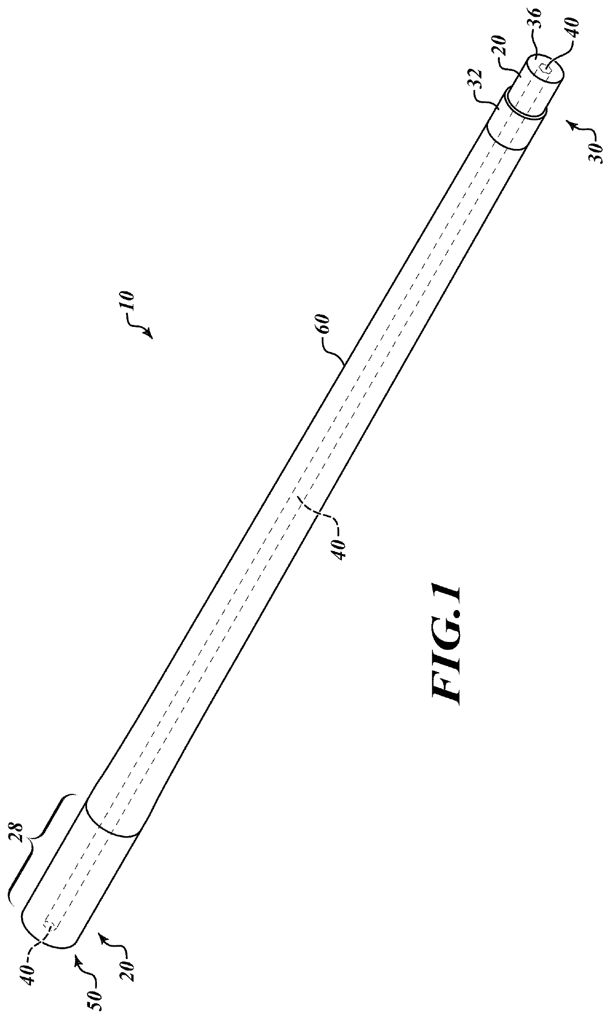
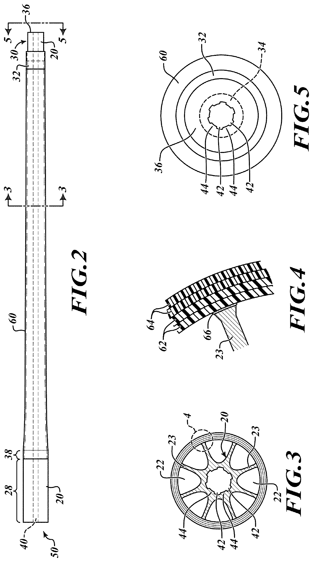
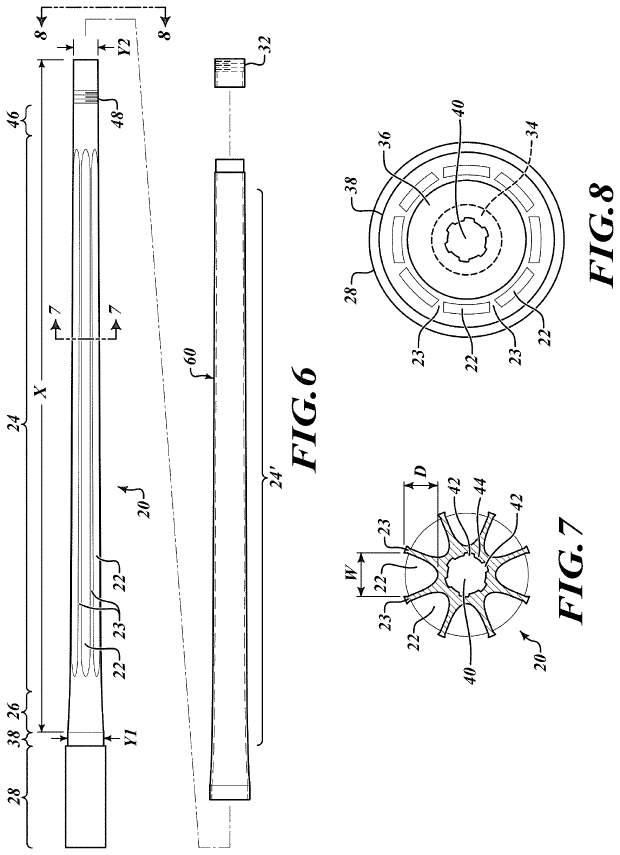
[0033]By way of overview, embodiments of the inventive method and rifle barrel are formed by a method with very tight control over the variables necessary to properly form the carbon fiber sheath that envelopes the barrel liner:[0034]1. Composite materials are wrapped around a tapered mandrel at a thickness prescribed for the specific contour / design. (There are numerous individual mandrel designs for different contours / configurations.) The dimensional relationship between the mandrel and the liner are such that the resulting composite “tube” is formed to achieve full contact with the steel barrel liner;[0035]2. The composites and resin material are cured to achieve the highest possible longitudinal stiffness, restricting hoops, and uniformity along the length of the formed sheath. Materials are selected to allow high temperature use;[0036]3. A structural steel liner is made to match the contour of the mandrel. The liner is “fluted” and material is removed by aggressive fluting while...


PUM

PropertyMeasurementUnit
elongation at breakaaaaaaaaaa
temperatureaaaaaaaaaa

Abstract

A method for forming and a carbon fiber barrel sleeve resiliently bonded to steel liner includes providing a rifle barrel having thickened walls and a mandrel blank. Each of the barrel and blank are turned to form a barrel liner and a mandrel, respectively, such that each has a substantially identical contour. The barrel liner is stress relieved to eliminate stresses within the molecular structure of the barrel liner. A plurality of flutes are cut into an exterior surface of the barrel liner; the depth of each flute being at least equal to the depth of the flute. A plurality of layers of carbon fiber fabric are laid up on the mandrel to form a sheath which is cured and bonded to the barrel liner with a continuous bond of high temperature adhesive at tips of the fins. The bonded sheath and barrel liner forming a rifle barrel.

Description

FIELD OF THE INVENTION[0001]The method for construction and resulting barrel assembly is disclosed as barrel formation technology, and specifically relates to formation of a barrel having a carbon fiber sheath.BACKGROUND OF THE INVENTION[0002]It has been long understood that a rifle's barrel changes shape and moves in multiple directions every time it is fired. These barrel motions coupled with shot to shot pressure variations greatly affect how well a particular barrel and load combination will shoot.[0003]Builders of accurate rifles agree if the barrel's movement cannot be eliminated, the next best thing is that it move consistently with each shot. That is why good shooting rifles have stiff barrels and their actions are firmly bedded in the stock while the stock is configured such that nothing touches the barrel in front of the receiver (free floating) eliminating any deformation of the barrel under the stress imparted by the shot pressure.[0004]Shooters often talk about another ...

Claims


Application Information

Patent Timeline
Patent Type & Authority Patents(United States)
IPC IPC(8): F41A21/02F41A21/20F41A21/44F41A21/24
CPCF41A21/02F41A21/20F41A21/24F41A21/44
Inventor SINNEMA, RONALD T.
Owner BENCHMARK BARRELS LLC
Why Eureka
Try Eureka