
Compact high-throughput device for water treatment

a high-throughput, compact technology, applied in water/sludge/sewage treatment, distillation, membranes, etc., can solve the problems of large inactive membrane area, low membrane packing density, and limited fresh water sources or rainwater, so as to reduce the inactive membrane area, prevent leakage, and increase the production capacity of a submerged module

Active Publication Date: 2021-08-10
KING ABDULLAH UNIV OF SCI & TECH
View PDF11 Cites 0 Cited by
  • Summary
  • Abstract
  • Description
  • Claims
  • Application Information

AI Technical Summary

Benefits of technology

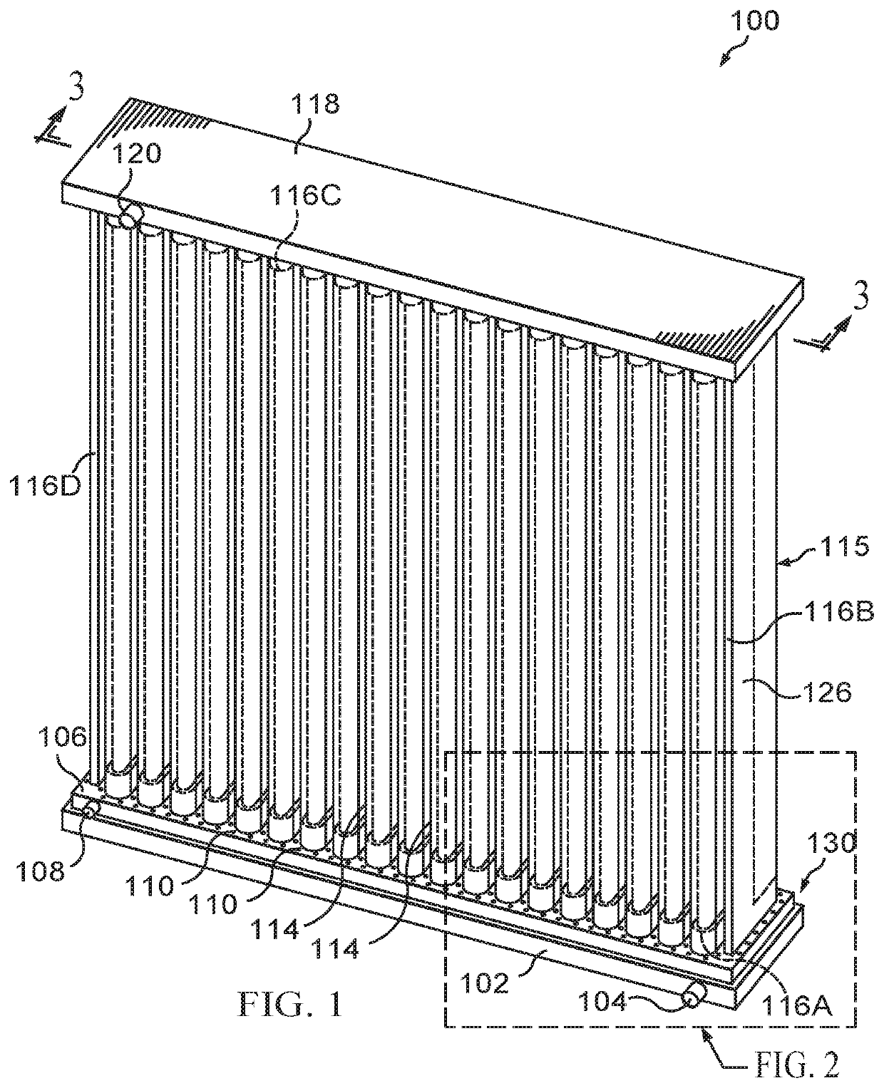
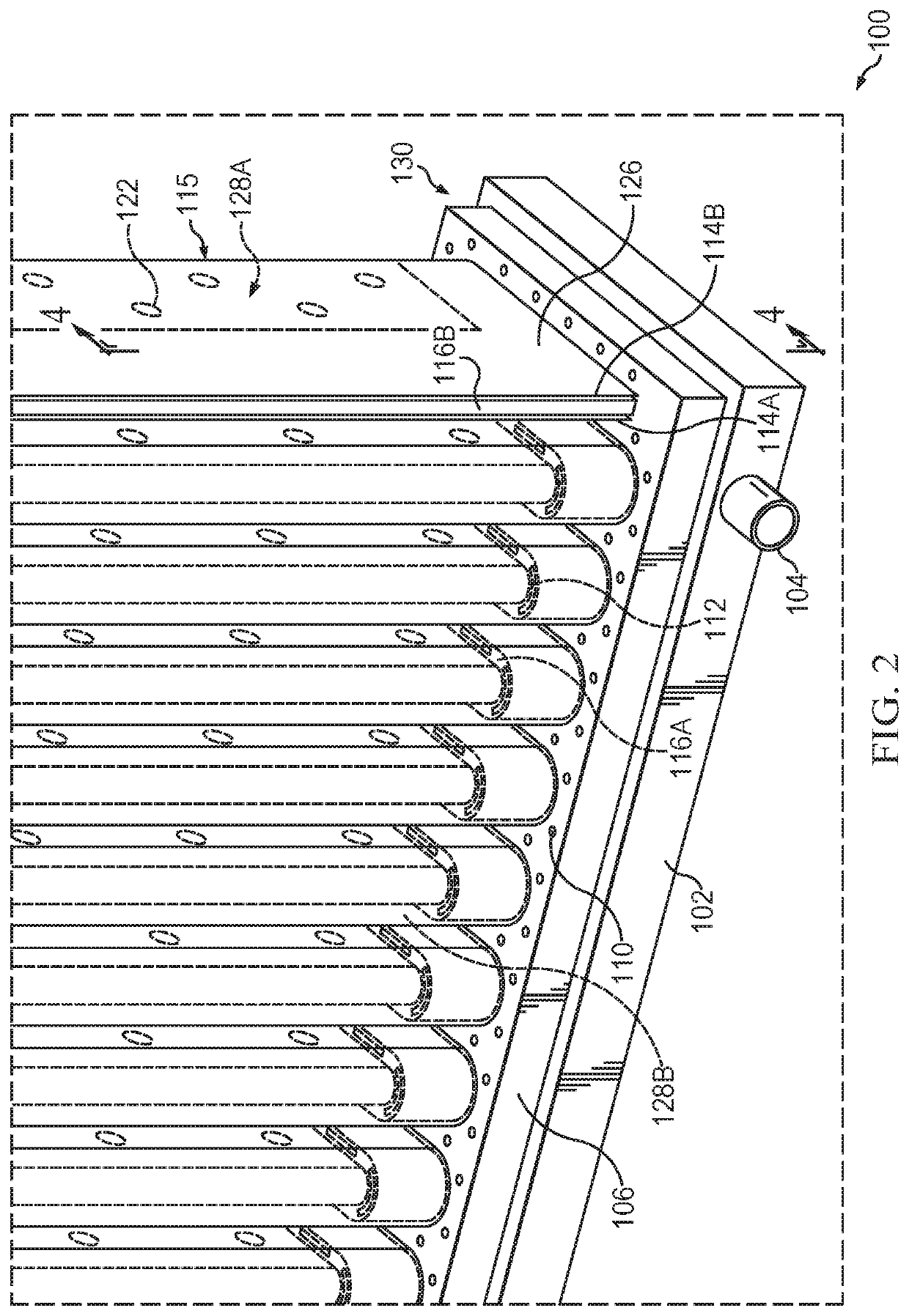
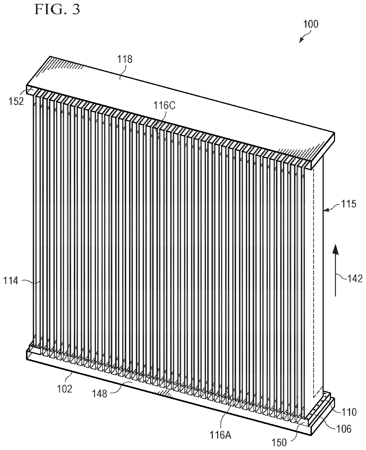
[0027]A corrugated membrane plate and frame module for use in fluid treatment applications is disclosed, where the corrugated design increases production capacity of a submersible module by more than 200% as compared to conventional submersible modules. The corrugated membrane plate and frame module can be a submersible or non-submersible module. The increase is achieved by tripling the membrane packing density per module using an optimized corrugated design. The disclosed corrugated membrane plate and frame also reduces the inactive membrane area per module, which is caused by deactivation of membranes edges attached to the plate and frame core in order to prevent leakage.
[0035]This module has an inlet and outlet for a single fluid that moves inside the module in total isolation from the outside fluid to which the module is exposed. The clean draw fluid (in forward osmosis) or coolant (in membrane distillation) runs through the lumen space created by the two sheets of membrane attached to the corrugated membrane plate and frame while the module is exposed to the lower-salinity feed fluid (wastewater). If the module is a submersible module, the module can be submerged in a tank containing the lower-salinity feed fluid and if the module is a non-submersible module, the lower-salinity feed fluid is provided to an inlet port of a housing of the module. The draw fluid or coolant induces the permeation of water through the membranes. Negative pressure, via vacuum or suction, can be used to facilitate movement of the draw fluid or coolant into the module and for removal of permeated materials from the fluid outlet manifold.
[0039]The method steps may also further comprise providing a fluid inlet manifold attached to the bottom frame member, said fluid inlet manifold having an interior space for receiving a fluid, a fluid inlet port, and an opening on a top surface adjacent to a plurality of openings in the bottom frame member which allow the fluid to flow into the membrane lumen space of the corrugated membrane plate and frame core, and said gas inlet manifold is positioned between the fluid inlet manifold and the bottom frame member, said gas being maintained in isolation from the fluid manifold and the membrane lumen space of the corrugated membrane plate and frame core; providing a conduit to deliver a fluid to the fluid inlet manifold via the fluid inlet port; and delivering a draw fluid or a coolant fluid to the fluid inlet manifold, said draw fluid or coolant fluid enhancing movement of permeated fluid into the membrane lumen space.

Problems solved by technology

Most of the interest in desalination focuses on production of fresh water for consumption and is particularly of interest in areas where seawater is abundant, but fresh water sources or rainwater may be limited.
Though saline water exists in abundance, unfortunately, desalinating seawater can be costly because a large amount of energy is consumed in the process.
There are two problem areas in the conventional water treatment membrane separation technology: low membrane packing density and large inactive membrane areas.
The conventional membrane plate design limits the active membrane area due to low membrane-packing density, eventually making it unfeasible in niche applications, such as the treatment of produced water from oil and gas industries using forward osmosis or membrane distillation.
The conventional design also causes significant loss of active membrane area due to the deactivation of membrane area caused by fixing the edges of the membrane sheets on several membrane elements used in a single module.
Fixing the edges is essential to maintain separation of permeate from the untreated fluid, however, this also results in a decrease in the effective membrane area available for a flat sheet membrane.

Method used


Image

  • Compact high-throughput device for water treatment
  • Compact high-throughput device for water treatment
  • Compact high-throughput device for water treatment

Examples


example 1

Calculations for Disclosed Corrugated Design

[0121]The design of the disclosed corrugated membrane plate and frame design was optimized using mathematical formulas derived from the geometric shapes of the corrugated membrane shown in FIGS. 8A-8D.

[0122]FIG. 8A shows a top view of a corrugated membrane sheet with a total number of turns equal to n. FIG. 8B is an enlargement of a corrugated turn on the central membrane plate. FIG. 8C is schematic of a front view of the membrane for the disclosed module. FIG. 8D schematic of a side view of the membrane for the disclosed module. With reference to FIGS. 8A-8D, the equations for calculating the total effective membrane area in the disclosed design are shown below, where:[0123]A1=Effective Membrane Area in the Corrugated Design[0124]Le=Effective length of the membrane sheets, excluding any attached lengths[0125]n=Number of turns per membrane element[0126]s=Spacing between turns[0127]t=Thickness of membrane plate frame on which two sheets of ...

example 2

Calculations for Conventional Flat Plate Design

[0159]In order to compare the total effective membrane areas between the disclosed submersible module (corrugated design) and a conventional plate and frame design having the same dimensions and footprint; the overall height, width and depth of the modules in both designs are kept equal. The spacing and thickness of the membrane plates are also kept the same between the two designs when calculating effective membrane areas.

[0160]FIG. 9A shows a schematic for the top view of a conventional design with flatsheet membranes with a total number of membranes equal to m. FIG. 9B is schematic of a front view of a membrane sheet for a conventional module. FIG. 9C is a schematic of a side view of membranes for a conventional module. With reference to FIG. 9A-9C, the equations for calculating the total effective membrane area in a conventional design are shown below, where:[0161]A2=Total effective membrane area per module in the conventional desig...

example 3

Calculations for Intermediate Design

[0174]For comparison, effective membrane area of an intermediate design was calculated. In the intermediate design, flat membrane plates would run along the shorter dimension of the module, instead of the longer side as in the conventional design, and would have the same dimensions and footprint; with the same overall height, width and depth used in the calculations for the disclosed submersible design and the conventional design, in order to provide a direct comparison of the membrane area. The intermediate design considered would have the same number of sheets as the number of turns on the corrugated design, but would have attached edges on all sides of the membrane sheets and no corrugations.

[0175]FIG. 10A shows a schematic for the top view of an intermediate design membrane sheet with a total number of membranes equal to m. FIG. 10B is schematic of a front view of membranes for an intermediate design. FIG. 10C is a schematic of a side view of ...


PUM

PropertyMeasurementUnit
areaaaaaaaaaaa
areaaaaaaaaaaa
pressureaaaaaaaaaa

Abstract

A corrugated membrane plate and frame module for use in fluid treatment applications is disclosed, where the corrugated design increases production capacity of a module by more than 200% as compared to conventional modules. The increase is achieved by tripling the membrane packing density per module using an optimized corrugated design. The disclosed corrugated membrane plate and frame also reduces the inactive membrane area per module, which is caused by deactivation of membranes edges attached to the plate and frame core in order to prevent leakage.

Description

RELATED APPLICATION DATA[0001]This application is a U.S. National Stage Application of International Application No. PCT / IB2018 / 054400, filed Jun. 14, 2018, which claims the priority and benefit of U.S. Provisional Patent Application Ser. No. 62 / 523,097, filed Jun. 21, 2017, the entire contents of which are incorporated herein by reference.TECHNICAL FIELD[0002]The present invention relates to an apparatus and method for water treatment.BACKGROUND OF THE INVENTION[0003]The background of this invention will address water treatment, membrane technology, and submersible membrane systems.[0004]Water Treatment[0005]Global population projected increases over the next few decades will require water and energy for domestic, agricultural and industrial consumption, all of which ultimately rely on a rapidly diminishing global water supply. With water use expected to grow by twice the rate of population growth, a 2013 United Nations report estimated that by 2050 most countries around the world ...

Claims


Application Information

Patent Timeline
Patent Type & Authority Patents(United States)
IPC IPC(8): B01D63/14B01D61/00B01D61/36C02F1/44B01D65/02C02F3/12
CPCB01D63/14B01D61/002B01D61/364C02F1/445B01D65/02B01D2313/125B01D2313/14B01D2313/243B01D2313/26B01D2321/18C02F3/1268B01D65/08B01D69/00B01D69/06C02F1/44B01D2325/06B01D61/025B01D61/027B01D61/145B01D61/147C02F1/441C02F1/442C02F1/444C02F1/447B01D61/0022B01D63/0822B01D69/1071B01D61/0021B01D61/3641
Inventor ABU-GHDAIB, MUHANNAD AMMARGHAFFOUR, NOREDDINE
Owner KING ABDULLAH UNIV OF SCI & TECH
Learn More