
Input error detection device

a technology of error detection and input, which is applied in the direction of electrical programme control, program control, instruments, etc., can solve the problems of incorrect entry of axis names, failure to enter decimal points, and errors in the number of digits, etc., and achieve the effect of accurate detection

Active Publication Date: 2021-08-24
FANUC LTD
View PDF12 Cites 0 Cited by
  • Summary
  • Abstract
  • Description
  • Claims
  • Application Information

AI Technical Summary

Benefits of technology

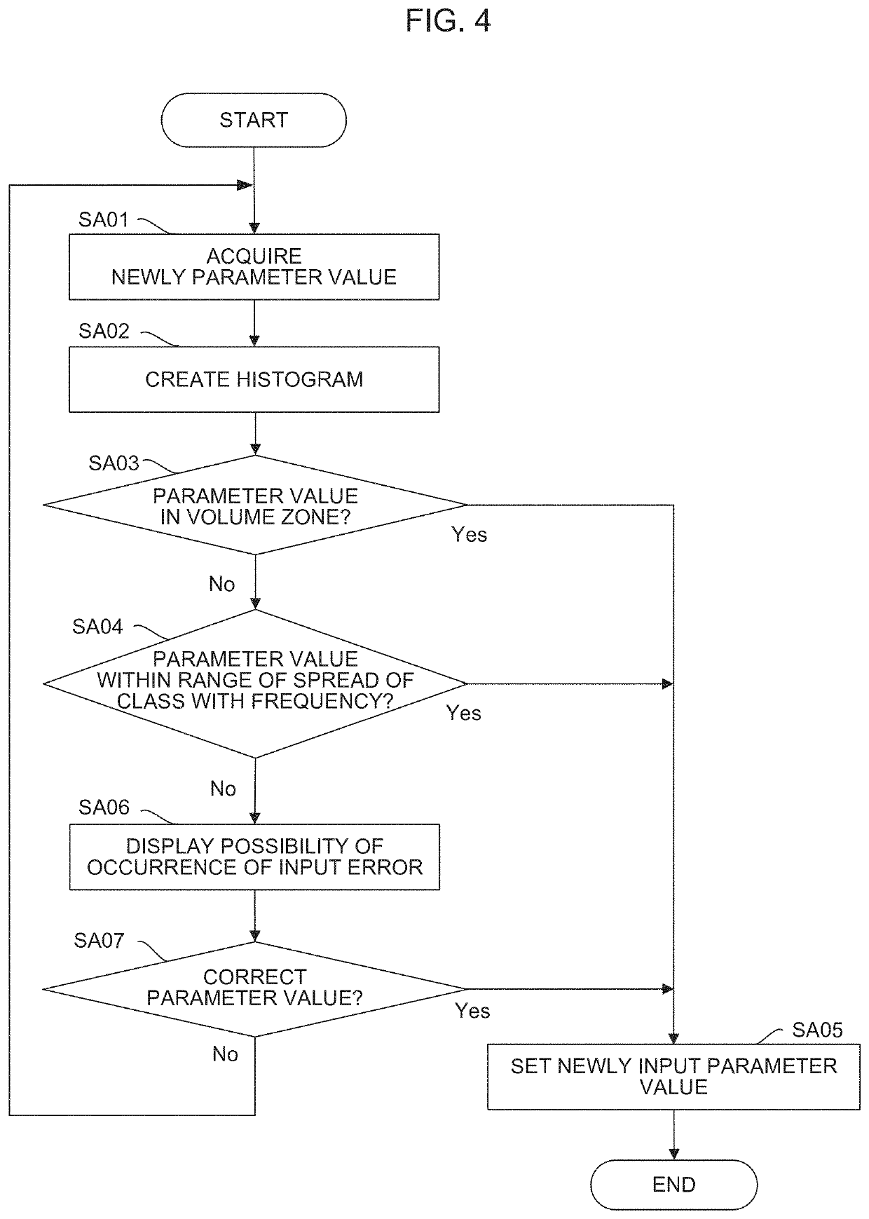
[0009]An input error detection device of the present invention solves the above problems by creating a histogram of input values and detecting a worker's input error based on comparison with the created histogram. The input error detection device of the present invention performs more advanced input error detection by catching the trend of input values using a histogram created based on values input in the past and a histogram created according to a control program position.
[0011]According to the present invention, an input error can be accurately detected even when different input trends exist mixedly for the same item. Moreover, advanced input error detection can be performed based on the whole trend of values, as well as on a simple deviation of an input range, wrong input of a decimal point, and the like.

Problems solved by technology

When coordinate values (command values) or offset values are input to a numerical controller for controlling a manufacturing machine such as a machine tool, there is a possibility of occurrence of failure to enter a decimal point, error in the number of digits (error in the number of zeros or the position of a decimal point), wrong entry of axis names, or the like.
Due to such an input error, the spindle of the manufacturing machine or the like may sometimes be broken by collision or damage a workpiece.
However, the values input to the numerical controller are not always be concentrated near specific values only.
Therefore, such a problem is caused that the machine coordinate values of a position between the vertex and center of the workpiece are inevitably determined to be correct, that is, the accuracy of incorrectness determination for the input value is reduced.
A similar problem also occurs when a tool offset value is set in a manufacturing machine that can handle a plurality of tools, for example.
Although the tool offset value varies depending on the tool type, the setting of the tool offset value in the manufacturing machine is not guaranteed with a set item for each tool type.
Therefore, also in this case, the technique disclosed in Japanese Patent Application Laid-Open No. 2003-295916 cannot ensure correct functioning of correctness determination of the input value.
However, in creating or correcting the control program, the spindle of the manufacturing machine or the like may sometimes be broken by collision or damage a workpiece due to an input error.
If the technique disclosed in Japanese Patent No. 3949689 is used to deal with this problem, although some input errors can be detected, they are only formal errors (input of values outside the range of specifications, wrong input of a decimal point, etc.).
Thus, there is such a problem that this technique functions only limitedly for input error detection from the view point of the trend of input values in the entire control program.

Method used


Image

  • Input error detection device
  • Input error detection device
  • Input error detection device

Examples


first embodiment

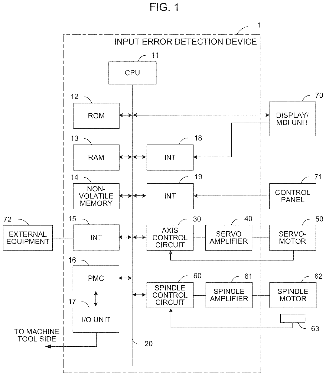
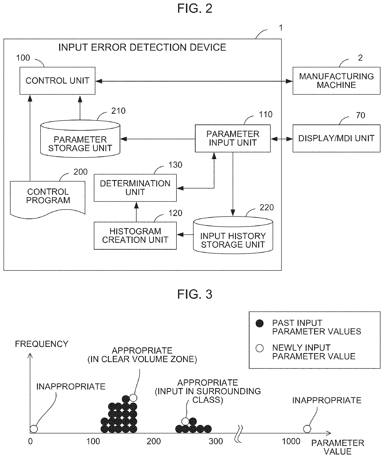
[0030]FIG. 2 is a schematic functional block diagram of the input error detection device 1 according to the Each of functional blocks shown in FIG. 2 is implemented as the CPU 11 of the input error detection device 1 shown in FIG. 1 executes the individual system programs and controls operations of the various parts of the input error detection device 1.

[0031]The input error detection device 1 of the present embodiment comprises a control unit 100, parameter input unit 110, histogram creation unit 120, and determination unit 130. The control unit 100 controls a manufacturing machine 2 based on a control program 200 and control parameters set in a parameter storage unit 210. The parameter input unit 110 accepts parameters input by a worker's operation of the display / MDI unit 70. The histogram creation unit 120 creates a histogram based on histories of the parameters that are input in the past. The determination unit 130 determines the propriety of parameters input from the parameter...

second embodiment

[0042]FIG. 5 is a schematic functional block diagram of an input error detection device 1 according to a Each of functional blocks shown in FIG. 5 is implemented as the CPU 11 of the input error detection device 1 shown in FIG. 1 executes the individual system programs and controls operations of the various parts of the input error detection device 1.

[0043]The input error detection device 1 of the present embodiment differs from the first embodiment in that a histogram is created based on numerical values such as coordinate values included in each block of the control program 200 and the propriety of each numerical value in the control program 200 is determined based on the created histogram. The input error detection device 1 of the present embodiment comprises a program editing unit 140 configured to edit the control program 200.

[0044]The program editing unit 140 of the present embodiment is a functional means for displaying the control program 200 on the display / MDI unit 70, acc...


PUM


Abstract

An input error detection device can detect an input error based on input values input in the past and the trend of values from the view point of the whole of a control program. In order to detect an error in inputting a value used to control a manufacturing machine, the input error detection device is provided with a histogram creation unit configured to create a histogram, based on a set of values used to control the manufacturing machine, and a determination unit configured, based on the histogram, to determine input errors of the values used to control the manufacturing machine.

Description

RELATED APPLICATION[0001]The present application claims priority to Japanese Application Number 2018-057026 filed Mar. 23, 2018, the disclosure of which is hereby incorporated by reference herein in its entirety.BACKGROUND OF THE INVENTIONField of the Invention[0002]The present invention relates to an input error detection device, and more particularly, to an input error detection device configured to detect an error in inputting data to be handled in a numerical controller.Description of the Related Art[0003]When coordinate values (command values) or offset values are input to a numerical controller for controlling a manufacturing machine such as a machine tool, there is a possibility of occurrence of failure to enter a decimal point, error in the number of digits (error in the number of zeros or the position of a decimal point), wrong entry of axis names, or the like. Due to such an input error, the spindle of the manufacturing machine or the like may sometimes be broken by collis...

Claims


Application Information

Patent Timeline
Patent Type & Authority Patents(United States)
IPC IPC(8): G05B19/4093G05B19/408G05B19/18
CPCG05B19/40937G05B19/182G05B19/408G05B2219/31103G05B19/406
Inventor SATOU, KOUJIOZEKI, SHINICHIITAKURA, SHINICHIROU
Owner FANUC LTD
Learn More