
Airborne infectious disease isolation units and method of making using prefabricated containers

Active Publication Date: 2021-08-31
UNITED STATES OF AMERICA THE AS REPRESENTED BY THE SEC OF THE ARMY
View PDF10 Cites 1 Cited by
  • Summary
  • Abstract
  • Description
  • Claims
  • Application Information

AI Technical Summary

Benefits of technology

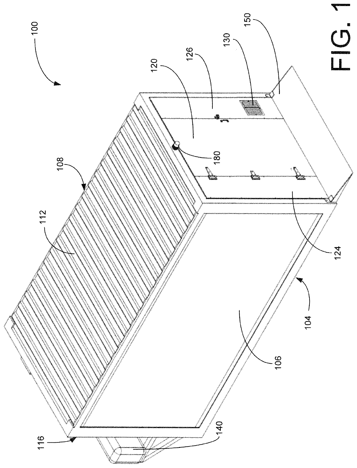
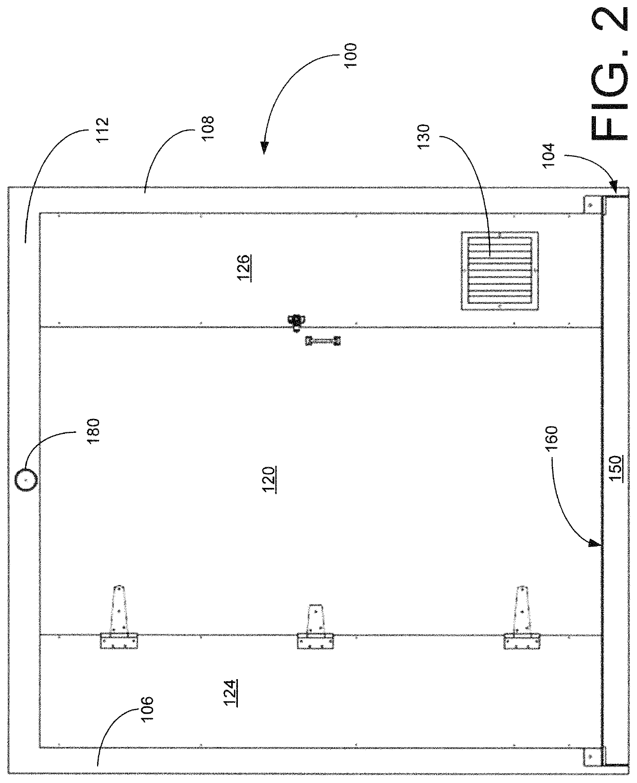
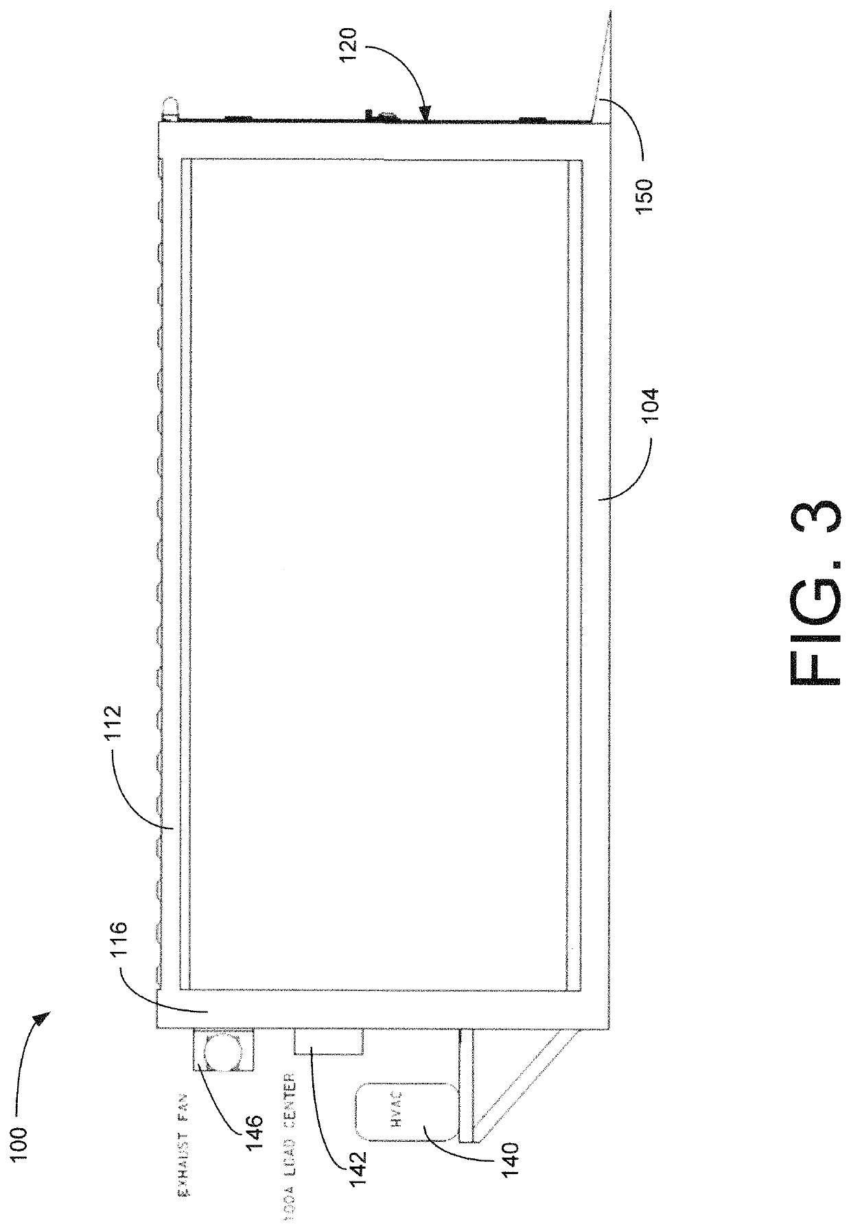
The present invention provides a quick and low-cost method of building airborne infectious isolation units using existing commercially available container units. These units can be used in a covered interior space, such as a large warehouse or sporting facility, that has existing utilities and other amenities. This invention allows for medical care personnel to not have to be completely equipped with PPE in every area of the enclosed building, but only within such containment units. The invention is directed to converting a commercially available prefabricated container into a self-contained infectious isolation treatment unit, sometimes referred to as an airborne infection isolation room (AIIR). The AIIR unit has a clear door, washable wall interiors, and floor coverings for easy cleaning and decontamination.

Problems solved by technology

The virus has caused widespread, global stay-home orders, leading to businesses and almost all civic human activities being curtailed or prohibited in unprecedented manner.
Global travel has come almost to a stop, and it has caused almost every economy in the world to experience profound distress.
Symptoms often include fever, cough, dizziness, and shortness of breath, and those with underlying medical conditions such as asthma, prior pneumonia, diabetes, hypertension, and heart conditions have high rate of mortality among the infected, often with the patients dying of respiratory distress and failure.
Because there are no proven vaccine or antiviral mediation for COVID-19, many infected patients end up needing medical care and in many cases intensive medical care.

Method used


Image

  • Airborne infectious disease isolation units and method of making using prefabricated containers
  • Airborne infectious disease isolation units and method of making using prefabricated containers
  • Airborne infectious disease isolation units and method of making using prefabricated containers

Examples


Embodiment Construction

[0038]Detailed illustrative embodiments of the present invention are disclosed herein. However, specific structural and functional details disclosed herein are merely representative for purposes of describing example embodiments of the present invention. The present invention may be embodied in many alternate forms and should not be construed as limited to only the embodiments set forth herein. Further, the terminology used herein is for the purpose of describing particular embodiments only and is not intended to be limiting of example embodiments of the invention.

[0039]As used herein, the singular forms “a,”“an,” and “the,” are intended to include the plural forms as well, unless the context clearly indicates otherwise. It further will be understood that the terms “comprises,”“comprising,”“includes,” and / or “including,” specify the presence of stated features, steps, or components, but do not preclude the presence or addition of one or more other features, steps, or components. It ...


PUM


Abstract

In one embodiment, a prefabricated container is modified as a medical isolation room by replacing an original door with a clear front door. An intake louver and an adjustable damper are disposed at a lower part of the front end. An exhaust vent is disposed at an upper part of the back wall. An exhaust fan and a HEPA filter are coupled to the exhaust vent. Washable coverings cover interior sides of the container to provide washable, nonslip interior surfaces. The exhaust fan and the adjustable damper at the intake louver are controlled to produce in the medical isolation room a negative air pressure of at least about minus 0.01 inch of water gage (approximately 2.5 pascals) and a displacement ventilation exhaust flow rate through the exhaust vent of at least about 100 cubic feet per minute (cfm) greater than an intake flow rate through the intake louver.

Description

CROSS-REFERENCE TO RELATED APPLICATIONS[0001]This application claims priority to U.S. Provisional Application 63 / 012,044, filed Apr. 17, 2020, which is incorporated herein by reference in its entirety.STATEMENT OF GOVERNMENT INTEREST[0002]The subject matter of this disclosure was supported by the U.S. Department of Energy and the U.S. Army Construction Engineering Research Laboratory. Under paragraph 1(a) of Executive Order 10096, the conditions under which this invention was made entitle the Government of the United States, as represented by the Secretary of the Army, to an undivided interest therein on any patent granted thereon by the United States. This and related patents are available for licensing to qualified licensees.BACKGROUNDField of the Invention[0003]The present invention relates to medical care rooms and, more particularly, to medical isolation rooms made by modifying commercially available prefabricated containers, which can be done quickly and inexpensively.Descript...

Claims


Application Information

Patent Timeline
IPC IPC(8): A61G10/02E04H1/12
CPCA61G10/02E04H1/1205E04H2001/1283E04H3/08A62B31/00
Inventor CHANNELL, MICHAEL GROGILLIO, DAVID MBLACKMON, MICKEY DRODEN, BRIAN CMERRY, BRYAN CBRAIDICH, DAVID J
Owner UNITED STATES OF AMERICA THE AS REPRESENTED BY THE SEC OF THE ARMY
Learn More