
Method and system for treating the surface of a vehicle

a vehicle surface and surface treatment technology, applied in the direction of vehicle exterior cleaning apparatus, etc., can solve the problems of insufficient consideration of mechanical parameters of the treatment element of the treatment brush, the movement parts of the system are subject to changes, and the motor will perform less efficiently and have a higher power input, so as to increase the speed of the treatment brush, the friction force between the treatment element and the reference surface is increased.

Active Publication Date: 2021-08-31
WASHTEC HLDG
View PDF5 Cites 2 Cited by
  • Summary
  • Abstract
  • Description
  • Claims
  • Application Information

AI Technical Summary

Benefits of technology

The method and system described in this patent allow for adjustment of treatment brush settings based on changes in material properties over time, ensuring consistent treatment results. This is possible because the system includes a brush spray guard that acts as a reference element, allowing for movement of the treatment brush in the direction of the brush spray guard for accurate reference measurements. This eliminates the need for a separate reference element and ensures stability of the brush spray guard for efficient use.

Problems solved by technology

During operation of a car wash system, the problem arises that moving parts of the system are subjected to changes due to use, aging, or wear.
Consequently, the motor will perform less efficiently and will have a higher power input.
The methods and treatment systems described in the state of the art have the drawback that changes in the mechanical parameters of the treatment elements of the treatment brush are not adequately taken into account.
This leads to a lower power input of the motor.
If, however, none of these adjustments is made, the treatment results will soon no longer be satisfactory.
On the other hand, on excessively close contact with the vehicle or at excessively high speeds of the treatment brush, damage to the vehicle components, e.g., external mirrors or windshield wipers, may occur.

Method used


Image

  • Method and system for treating the surface of a vehicle

Examples


Embodiment Construction

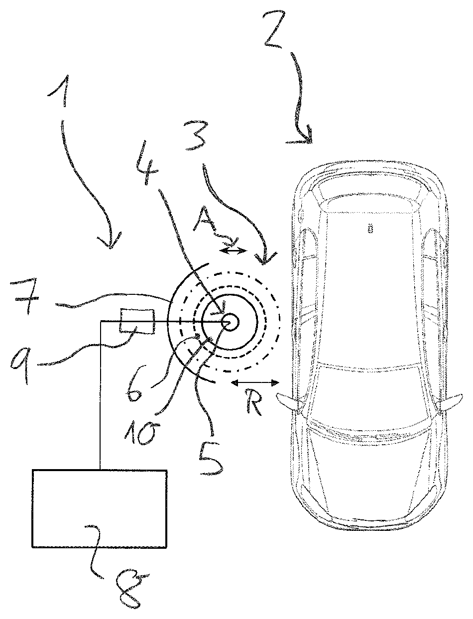
[0033]The embodiment example described below refers to a car wash system 1 for a vehicle 2. This system can be a conveyor tunnel car wash or a gantry-type car wash system.

[0034]The car wash system 1 comprises a washing brush 3 which serves as a treatment brush and which is pivotally mounted about a rotary shaft 5. In the embodiment example shown, the washing brush 3 is a washing brush for the side of the car. The rotary shaft 5 is connected to a motor 4 which serves as the drive motor for the rotational movement of the washing brush 3. Radially mounted on the outside of the washing brush 3 are treatment elements 6 known in the art which are attached to a carrier element 10. In FIG. 1, with the washing brush 3 at rest, the circumference formed by the treatment elements 6 is represented by a broken line. During rotation of the washing brush 3, the treatment elements 6 are driven outwardly by the centrifugal force. In the FIGURE, with the washing brush 3 in operation, the circumference...


PUM


Abstract

A method for treating the surface of a vehicle by means of at least one rotating treatment brush. The treatment brush comprises treatment elements, the surfaces of which are brought into frictional contact with the vehicle surface during the treatment. According to the method, a reference measurement is carried out, in which the treatment brush is set in rotation and is moved into a defined position relative to a reference element, such that the surfaces of the handling elements are brought into frictional contact with the surface of the reference element, and in this case the value of the frictional force is measured directly or indirectly. During the treatment of the vehicle surface, the treatment brush is controlled as a function of the value of the frictional force measured during the reference measurement. A system for treating the surface of a vehicle by means of which this method can be carried out.

Description

FIELD OF THE INVENTION[0001]The present invention relates to a method for treating the surface of a vehicle, wherein a vehicle surface is treated by means of at least one rotating washing brush, said washing brush comprising treatment elements, the surfaces of which are brought into frictional contact with the vehicle surface during the treatment. The present invention also relates to a system for treating the surface of a vehicle by means of a washing brush which is pivotably mounted about a rotary shaft and which comprises a motor connected to the rotary shaft and treatment elements for frictional contact with the vehicle surface. The system for treating the surface of a vehicle is, in particular, a car wash system.BACKGROUND OF THE INVENTION[0002]During operation of a car wash system, the problem arises that moving parts of the system are subjected to changes due to use, aging, or wear. To ensure a satisfactory treatment result or, more specifically, a satisfactory washing result...

Claims


Application Information

Patent Timeline
Patent Type & Authority Patents(United States)
IPC IPC(8): B60S3/06
CPCB60S3/06
Inventor AUER, ROBERTCONRAD, FERDINAND
Owner WASHTEC HLDG
Learn More