Display apparatus and method for assembling the same

a technology of display apparatus and assembly method, which is applied in the field of display apparatus, can solve the problems of reducing image quality, affecting the appearance of the display panel, so as to prevent degradation of image quality, reduce distortion of the display cell fixed to the rear surface of the cover panel, and accurately set the shape and flatness of the cover panel

Active Publication Date: 2021-09-07
ALPINE ELECTRONICS INC
View PDF7 Cites 0 Cited by
  • Summary
  • Abstract
  • Description
  • Claims
  • Application Information

AI Technical Summary

Benefits of technology

[0022]According to the present disclosure, the frame-shaped reinforcement member is fixed to the rear surface of the cover panel. Therefore, the shape and flatness of the cover panel can be accurately set by the reinforcement member, and distortion of the display cell fixed to the rear surface of the cover panel can be reduced. Therefore, degradation of the image quality can be prevented.
[0023]In particular, when the cover panel has a three-dimensional shape including a bent portion or a curved portion, by fixing the reinforcement member to the rear surface of the cover panel, the dimensional accuracy of the three-dimensional shape of the cover panel can be maintained at a high level, and the flatness of the cover panel can also be maintained at a high level in a region in which the display cell is fixed. Therefore, distortion of the display cell, which is bonded to the cover panel over the entire area thereof, can be reduced.

Problems solved by technology

According to the electronic device having the above-described structure, when the panel is fixed to the support portion, the panel is easily distorted due to the flatness tolerance of the panel or the tolerance in formation of the support portion.
Accordingly, the display may be distorted and cause a reduction in the image quality.
In particular, when the panel and the display are large, the display is distorted to a large degree and over a large area due to the panel, and the image quality is significantly reduced.
Since the liquid crystal display apparatus is structured such that the reinforcement plate bonded to the liquid crystal cell is placed on the projecting portion of the intermediate frame with the cushioning material provided therebetween, the transparent reinforcement plate is not easily warped.
Therefore, the liquid crystal cell cannot be stably fixed.
In addition, in the case where a touch sensor or the like is placed on the front surface of the liquid crystal cell, the liquid crystal cell moves when a finger touches the display screen, and the touch sensor cannot be easily operated.

Method used


Image

  • Display apparatus and method for assembling the same
  • Display apparatus and method for assembling the same
  • Display apparatus and method for assembling the same

Examples


Embodiment Construction

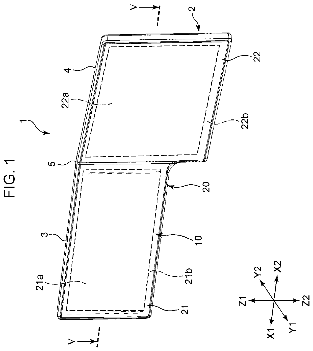
[0031]FIGS. 1 to 7 illustrate a display apparatus 1 mounted in a vehicle. In FIGS. 1 to 7, the Y1 direction is forward, which is a displaying direction, and the Y2 direction is rearward. The X1 direction is leftward, the X2 direction is rightward, the Z1 direction is upward, and the Z2 direction is downward.

[0032]The display apparatus 1 is fixed to an instrument panel or a dashboard located at the front of a cabin of an automobile or to a center console when in use. The display apparatus 1 is installed such that the Z1-Z2 direction thereof is vertical or at an angle such that the bottom thereof is shifted forward.

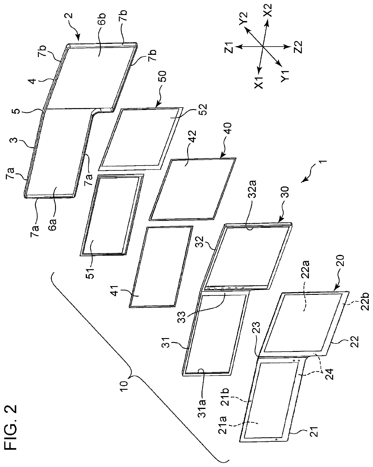
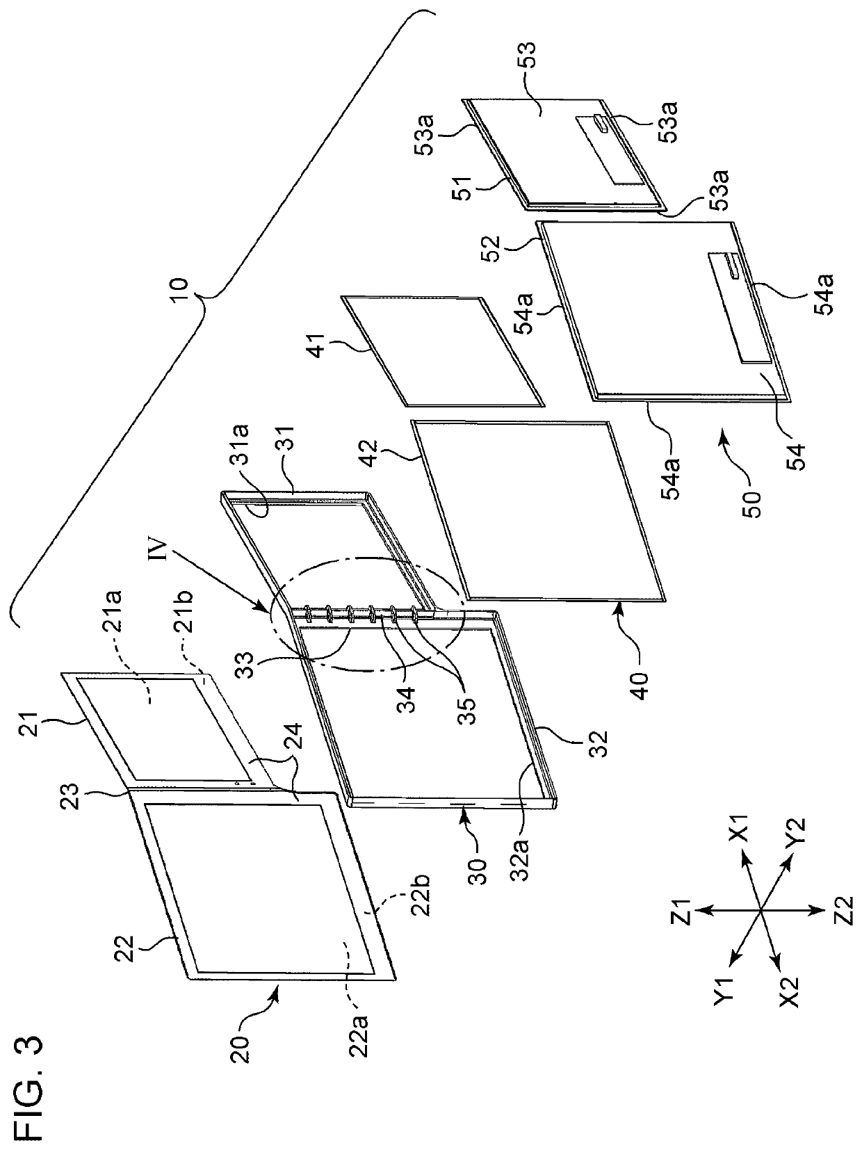
[0033]As illustrated in FIGS. 1 and 2, the display apparatus 1 includes a rear support member 2 disposed at the rear and a display panel assembly 10 disposed in front of the rear support member 2. The display apparatus 1 is mounted in the vehicle by fixing the rear support member 2 to a portion of a vehicle body. As illustrated in FIGS. 2 and 3, the display panel assembly 1...


PUM

PropertyMeasurementUnit
total light transmittanceaaaaaaaaaa
rigidityaaaaaaaaaa

Abstract

A frame-shaped reinforcement member is bonded and fixed to a rear surface of a cover panel, such as a glass plate. The reinforcement member has a rigidity higher than that of the cover panel. Since the reinforcement member is provided, the flatness of flat portions of the cover panel can be maintained at a high level. The reinforcement member is bonded and fixed to a rear support member after display cell elements are bonded to the flat portions and backlights are fixed to the reinforcement member.

Description

RELATED APPLICATION[0001]The present application claims priority to Japanese Patent Application Number 2019-085415, filed Apr. 26, 2019, the entirety of which is hereby incorporated by reference.BACKGROUND1. Field of the Invention[0002]The present invention relates to a display apparatus mounted in a vehicle, for example, and including a light-transmissive cover panel and a display cell fixed to a rear surface of the cover panel, and also relates to a method for assembling the display apparatus.2. Description of the Related Art[0003]Japanese Unexamined Patent Application Publication No. 2013-219518 describes an invention relating to an electronic device including a display.[0004]This electronic device includes a display and a panel larger than the display. The panel is fixed to a front surface of the display with a transparent adhesive. A portion of the panel that protrudes from the display is fixed to a front surface of a support portion provided behind the display with an adhesive...

Claims


Application Information

Patent Timeline
Patent Type & Authority Patents(United States)
IPC IPC(8): G02F1/1333G02F1/1335G02F1/13357
CPCG02F1/133308G02F1/133524G02F1/133608G02F1/13332G02F1/133314G02F1/133317G02F1/133322G02F1/133325G02F1/133331G02F2202/28G02F2201/54G02F1/133328
Inventor MOCHIJI, HIROYUKIHARA, SATOSHI
Owner ALPINE ELECTRONICS INC
Why Eureka
Try Eureka