
Inflatable shock-absorbing sole structure

a sole structure and shock absorption technology, applied in the field of footgear, can solve the problems of running harm to one's knees or ankles, physiological and psychological damage, and the current air-cushion sneaker fails to adjust the pressure and hardness of the air-cushion, so as to improve the shock absorption effect, prevent the sole from rolling over, and improve the wear comfort

Active Publication Date: 2021-10-05
ZHEJIANG GEELY HLDG GRP CO LTD +1
View PDF53 Cites 2 Cited by
  • Summary
  • Abstract
  • Description
  • Claims
  • Application Information

AI Technical Summary

Benefits of technology

The present disclosure provides an inflatable shock-absorbing sole structure with an built-in air-charging device. This allows for easy adjustment of the airbag pressure and hardness to different road conditions and improves wearing comfort. The sole structure consists of an airbag room and an airbag mounted in the sole, providing better shock absorption. Connecting tubes are used to connect two airbags in each row, which prevents sole rollover and even spraining ankles. A removable anti-wear block is set on the sole, forming a modular sole structure that can be replaced when worn out, avoiding economic loss and improving walking posture.

Problems solved by technology

However, running may also bring harm to one's knees or ankles.
Once the harm occurred, it may take one week or even longer for the runner to recover, which will further cause physiological and psychological damages to him.
However, current air-cushion sneaker fails to or is not convenient to adjust the pressure and the hardness of the air-cushion.

Method used


Image

  • Inflatable shock-absorbing sole structure
  • Inflatable shock-absorbing sole structure
  • Inflatable shock-absorbing sole structure

Examples


embodiment 1

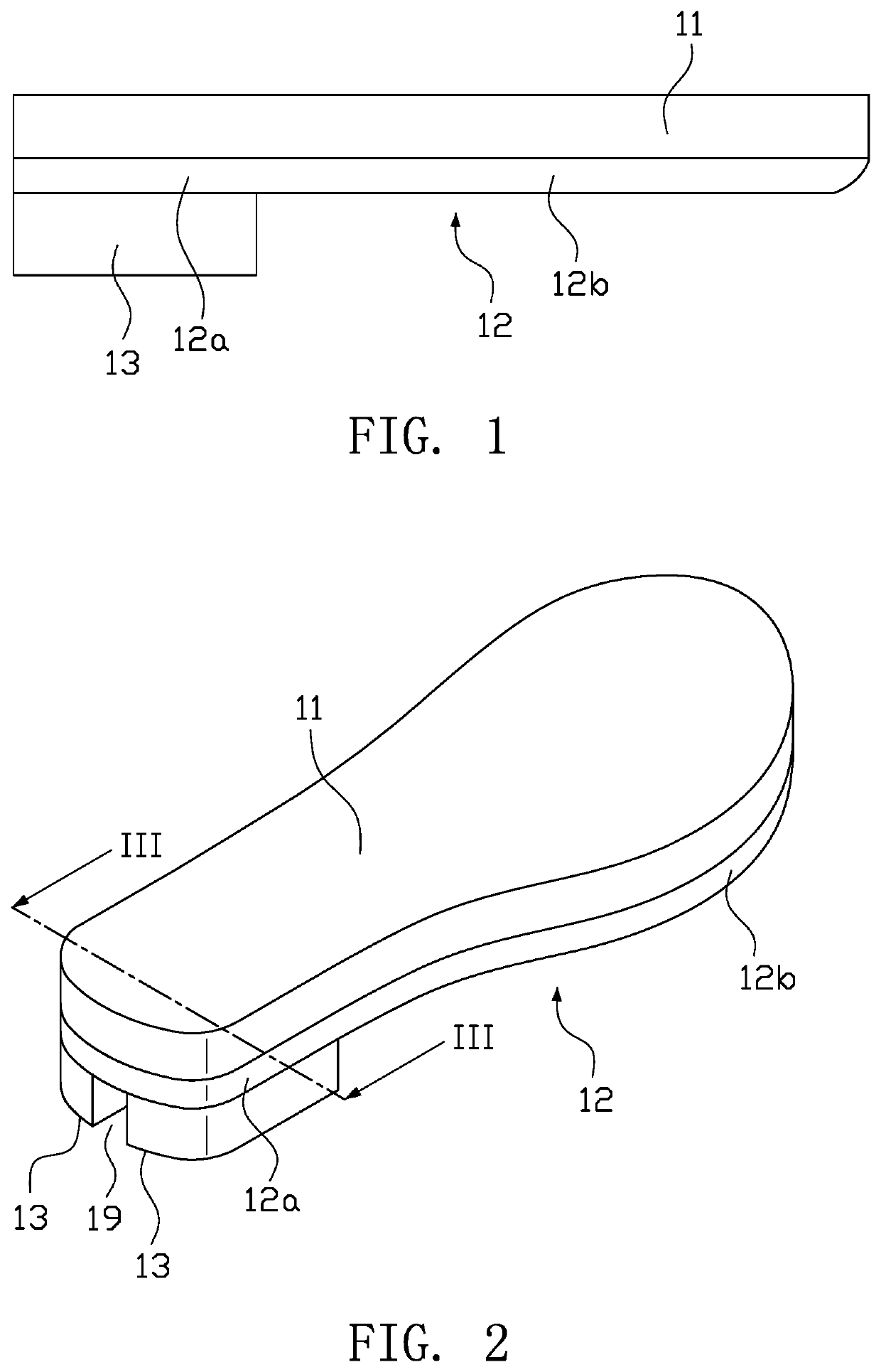
[0051]FIG. 1 illustrates a front view of the sole structure in embodiment 1 of the present disclosure, and FIG. 2 is an assembled isometric view of the sole structure in FIG. 1. Please referring to FIGS. 1 and 2, the sole structure in this embodiment includes a shoe insert 11 and a sole 12, at least one protrusion 120 is arranged on the sole 12, and a removable anti-wear block 13 is mounted on the bottom surface of the protrusion 120 near the ground, which adapts to the protrusion 120. The shoe insert 11 is placed on the sole 12, and it can also be omitted according to actual situations.

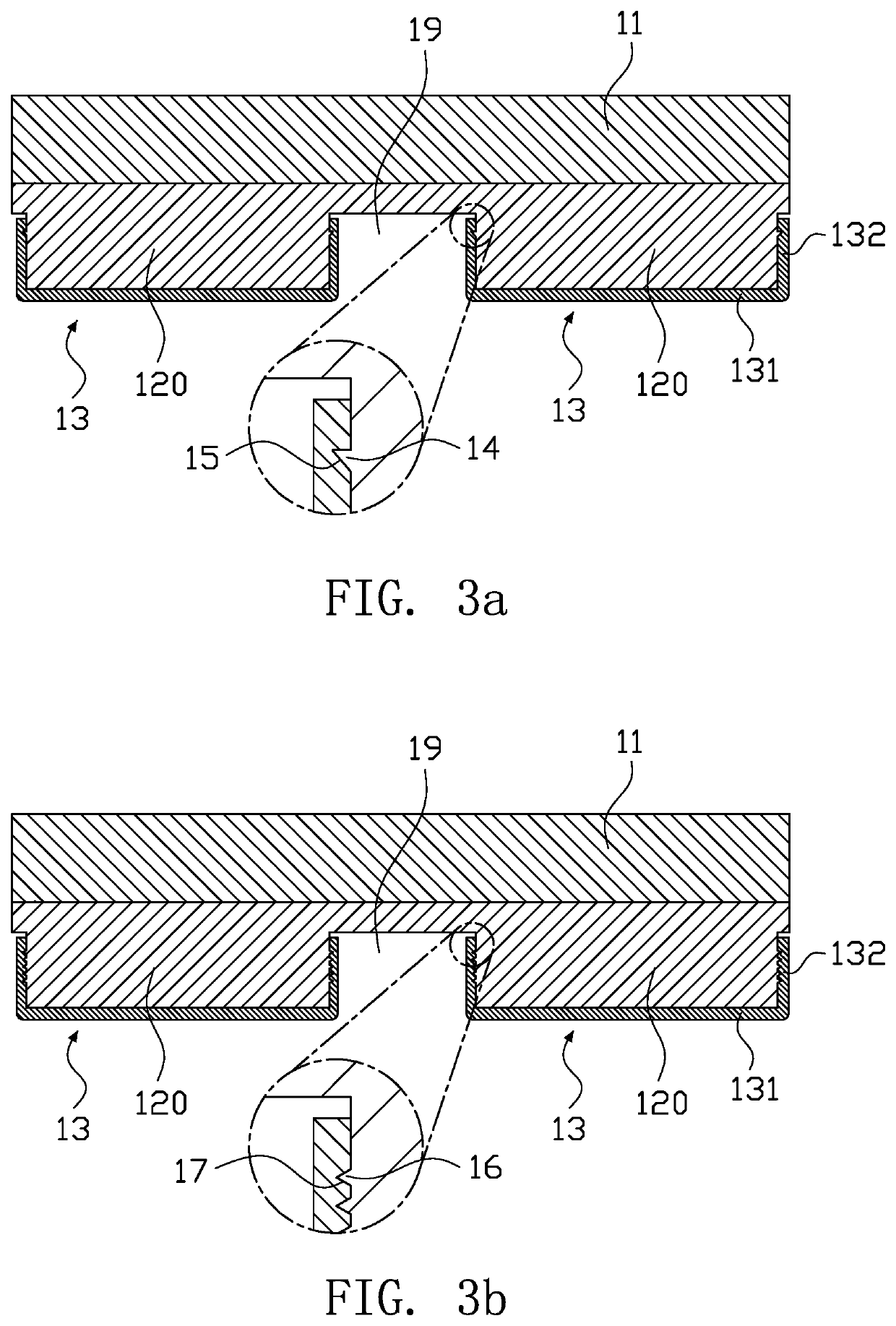
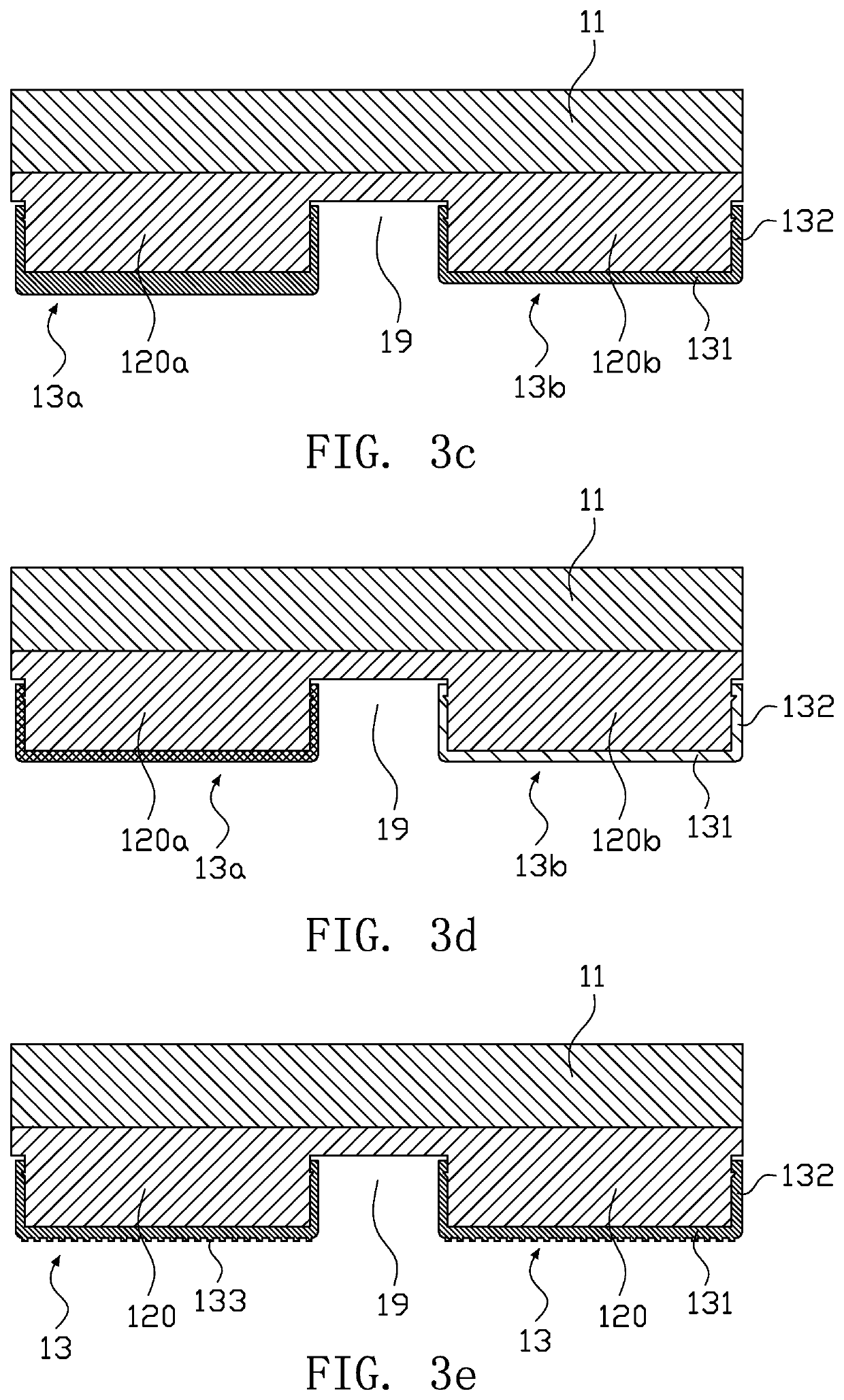
[0052]FIGS. 3a-3e are cross sectional views of FIG. 2 along direction. Please referring to FIGS. 3a-3e, the anti-wear block 13 includes an anti-wear pad 131 and fixing fins 132, the anti-wear pad 131 contacts with the ground and the fixing fins 132 are placed at the periphery of the anti-wear pad 131 and connected with the anti-wear pad 131, the anti-wear block 13 is removably fixed onto the protrusi...

embodiment 2

[0059]FIG. 4 is a front view of the sole structure in embodiment 2 of the present invention, FIG. 5 is an exploded schematic view of the sole structure in FIG. 4, FIG. 6 is an assembled schematic view of the sole structure in FIG. 4, and FIG. 7 is a cross-sectional view of FIG. 6 along VII-VII direction. Please referring to FIGS. 4-7, in this embodiment, an airbag room 121 is formed in the protrusion 120, and an airbag 21 is arranged in the airbag room 121, the airbag room 121 and the airbag 21 are stretchable and compressible. The airbag room 121 and the airbag 21 can be mounted in some of the protrusions 120 or be mounted in all of the protrusions 120. The arrangement of the airbag room 121 and the airbag 21 in the protrusion 120 can effectively improve the shock absorption effect of the sole structure. Further, compared with the solution wherein merely airbag room 121 is arranged, the embodiment wherein the airbag 21 is arranged in the airbag room 121 greatly reduces the leakage ...

embodiment 3

[0060]FIG. 8 is an exploded schematic view of the sole structure in embodiment 3 of the present disclosure, FIG. 9 is a bottom view of the shoe insert of the sole structure in FIG. 8, FIG. 10 is an assembled schematic view of the sole structure of FIG. 8, and FIG. 11 is a cross-sectional view of FIG. 10 along XI-XI direction. Please referring to FIGS. 8-11, in this embodiment, every two of the protrusions 120 are arranged in a row along the left-to-right direction of the sole 12 (X direction in FIG. 8), and the airbags 21 in every two protrusions 120 in each row are connected by a connecting tube 22. Specifically, multiple rows of protrusions 120 can be arranged along the fore-and-aft direction (Y direction in FIG. 8) of the sole 12, both protrusions 120 in each row are arranged along the left-and-right direction of the sole 12, and the airbags 12 in protrusions 120 of each row are connected by a connecting tube 22.

[0061]During daily exercises, the sole will turn over with a certain...


PUM


Abstract

The present disclosure provides an inflatable shock-absorbing sole structure, which includes a sole and at least one convex arranged on the sole, an airbag room is formed in the convex, and an airbag is arranged in the airbag room, the airbag room and the airbag are stretchable and compressible. The shock-absorbing sole structure further includes a built-in air-charging device, when the airbag needs to be inflated, the air-charging device can inflate it. The present disclosure provides a shock-absorbing sole structure, the airbag room and the airbag form a shock absorption system in the sole structure, which endows the sole structure a better shock absorption effect. Further, by mounting a built-in air-charging device in the sole structure, when the air bag needs to be inflated, the built-in air-charging device can inflate it.

Description

CROSS REFERENCE TO RELATED APPLICATION[0001]The present application is a 35 U.S.C. § 371 National Phase conversion of International (PCT) Patent Application No. PCT / CN2017 / 075878, filed on Mar. 7, 2017, which is based on and claims priority of Chinese patent application No. 201610642634.6, filed on Aug. 8, 2016. The entire disclosure of the above-identified application, including the specification, drawings and claims are incorporated herein by reference in its entirety. The PCT International Patent Application was filed and published in English.FIELD OF THE INVENTION[0002]The present disclosure relates to a footgear field, particularly relates to an inflatable shock-absorbing sole structure.BACKGROUND OF THE INVENTION[0003]With the improvement of living standards, more and more people begin to think much of their health and exercises. As one of the most popular exercises, running is gradually changing people's daily leisure life. With the national rise of marathon fever, more and m...

Claims


Application Information

Patent Timeline
Patent Type & Authority Patents(United States)
IPC IPC(8): A43B13/20A43B3/00A43B13/24A43B13/36A43B21/28
CPCA43B13/203A43B3/0005A43B13/206A43B13/24A43B13/36A43B21/285A43B13/20A43B13/22A43B3/44A43B3/48A43B3/246
Inventor LI, SHUFU
Owner ZHEJIANG GEELY HLDG GRP CO LTD
Learn More