
Revolving drum type digital lens printing device

a drum type, digital inking technology, applied in printing, other printing devices, domestic objects, etc., can solve the problems of inability to solve the above mentioned problems, the ink quality is always poor, and the long travel of the spray ink point is easily disturbed by the airflow in the environment, etc., to achieve good inking quality and high inking efficiency

Active Publication Date: 2021-10-12
TOPLENS HANGZHOU
View PDF5 Cites 1 Cited by
  • Summary
  • Abstract
  • Description
  • Claims
  • Application Information

AI Technical Summary

Benefits of technology

[0011]The object of the present invention is to solve the above problems and provide drum-type lens digital inking device with good inking quality and high inking efficiency.
[0024]The beneficial effects of the present invention are as follows. The inking quality of the invention is good, and the inking quality is better than that of the conventional inking machine. The invention is set with a drum, and the lens is mounted on the drum, with the drum rotation. Using the rotating circumference of the drum, to completely or partially compensate the curvature of the base curve of lens. When the radius of the front curve of the lens is just the same as the radius of the rotating circumference, it is 100% compensation. When there is a difference between the radius of the base curve of lens and the radius of the rotating circumference, it is partially compensated. Those two cases result in the print head drops to the lens center and to the edge reduced what compared to existing technologies, it is improves the quality of the inking.
[0025]When inking lens according to the invention, the lens does not easily touch the print head. The invention is provided with a lens height adjustment unit Because different lenses have different vertex heights. If no adjustment is made, the lens is easy to touch the print head at the inking workstation. To control the distance between the highest point of the lens and the print head with a lens height adjustment unit within 1 mm. Meanwhile, the closer the lens is to the print head, the better the inking effect.
[0026]The various steps of the digital inking of the present invention can be carried out in parallel to improve efficiency. For digital inking general several steps, such as lens loading-unloading, invisible marking recognition, digital inking, ink curing has been arranged different station design, each station arranged around the drum circumference, easy to achieve automation. When multiple lens holding mechanisms are provided on the drum, the lenses are stored in different workstation, it means that different cycle can be performed at the same time, which greatly improves the efficiency.
[0027]The invention can double the inking efficiency and greatly increase the capacity. The invention adopts the design of the left and right double print head station, this is two identical station units are set on the circumference of the drum. It means double the efficiency, and even can be arranged side by side with multiple print heads, can improve efficiency very well. If twin print heads design with left and right layout is used, the capacity of the digital print mirror can be increased to about 600 per hour, while the ordinary inking machine, as described in the Chinese patent 201310172713.1, is only about 120 pair per hour in efficiency, thus increasing capacity by 5 times.

Problems solved by technology

At present, all the print technologies for digital inking are designed for inking flat patterns But progressive lenses have a curved surface Different base curve, the lens height difference between the edge and the middle may be about 10 mm spray ink point from print head of print head has been diverged at that distance, and the long travel of the spray ink point is also easily disturbed by the airflow in the environment.
Inking quality is always not good for such big different in lens height between middle and edge.
Chinese patent 201310172713.1 discloses a digital lens inking printer, although the digital pattern inking of the lens surface is now available, but the above mentioned problems cannot be solved.
Due to the spray point is not inked along the normal direction of the surface, there is a problem of projection ejection.
The larger the base curve, the rate of decline is more severe.
The same resolution of 400 DPI may work well on lenses with smaller base curve, but at high base curve lens, the effect may not be very satisfactory.
In the left-right direction, the difference between the print head and the lens is relatively large, and the inking effect is often worse than the up-down direction.
Of course best way is to utilize single print head with a point-by-point 3-dimensional surface scan, but this speed is too slow not to meet the actual production needs.

Method used


Image

  • Revolving drum type digital lens printing device
  • Revolving drum type digital lens printing device
  • Revolving drum type digital lens printing device

Examples


embodiment 1

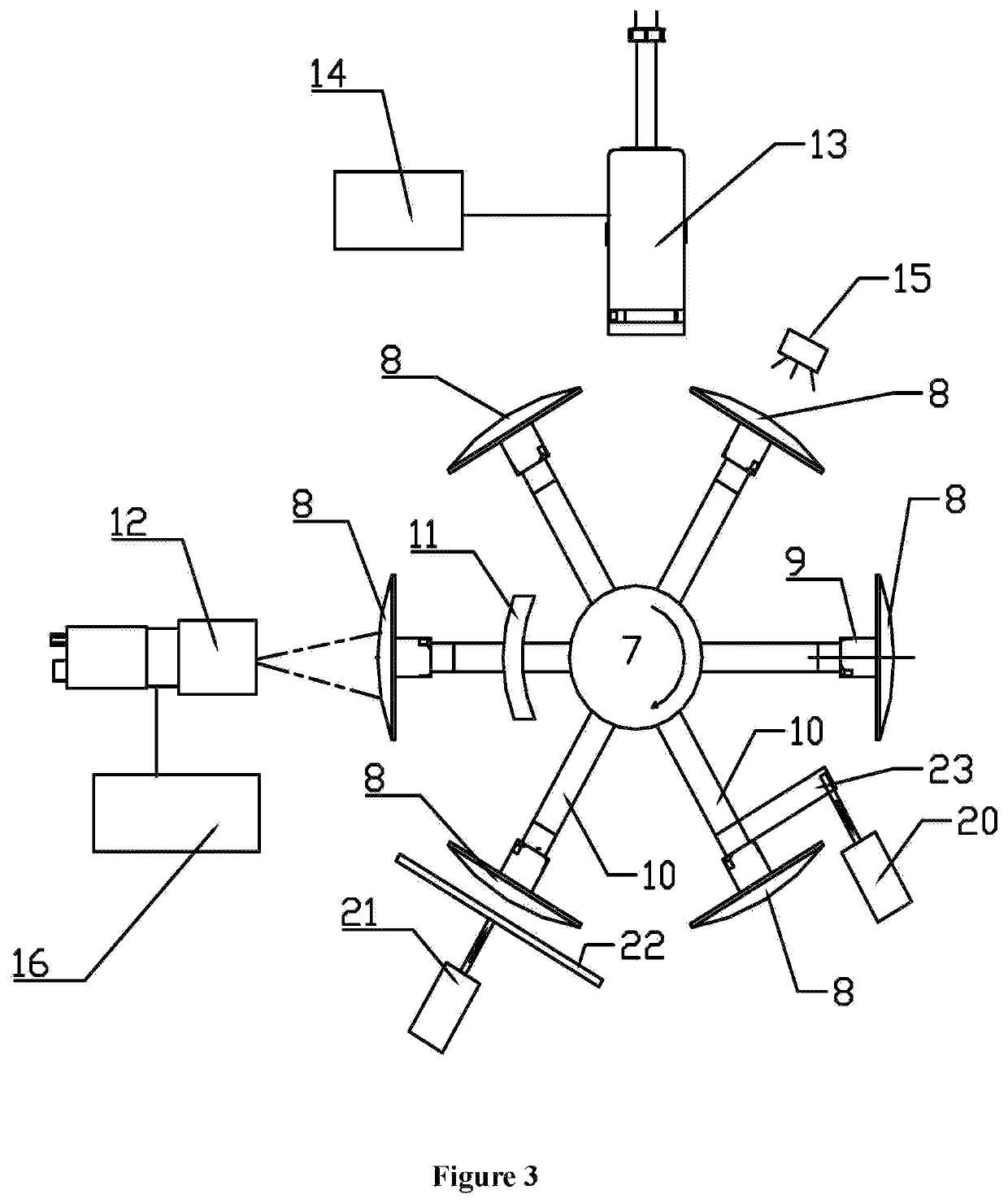
[0037]The embodiment is a single print head drum lens digital inking device, as shown in FIG. 3. This embodiment is a drum-type lens digital Inking device. Inking device includes rotating unit, lens height adjustment unit, invisible mark recognition unit, inking unit and ink curing unit.

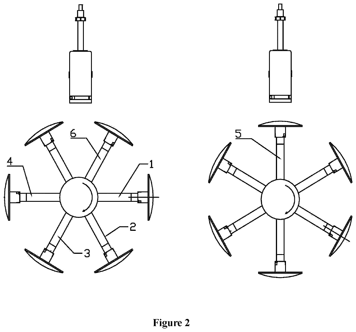
[0038]As shown in FIG. 2, the rotating unit includes a rotating drum 7 and a motor. The circumference of the drum 7 is evenly arranged with six lens holding mechanism, each lens holding mechanism includes a damping telescopic shaft 10, each damping telescopic shaft 10 is equipped with a vacuum suction for holding lens 8, and the vacuum suction head is connected to the vacuum generator 17.

[0039]The periphery of the drum 7 is provided with a lens loading-unloading workstation 1, a lens height adjustment workstation, an invisible mark recognition workstation 4, Inking station 5 and ink curing station 6 around the drum 7 is a circumference distribution. The principle is to use the rotation circumference ...

embodiment 2

[0048]This embodiment is a dual-print head drum-type lens digital inking device, as shown in FIG. 4. This embodiment is compared to the first embodiment, and its difference is that it the dual-print head left and right workstation design, the two rotary lens digital inking devices are combined on one drum 7. The embodiment is a drum-type lens digital inking device, characterized in that the inking device comprises a rotating drum unit, a lens height adjustment unit, invisible mark recognition unit, inking unit and ink curing unit.

[0049]As shown in FIG. 2, the rotating drum unit includes a rotating drum 7 and a motor, and six lens holding mechanism uniformly disposed on the rotation circumferential of drum. Each lens holding mechanism includes a damper telescopic shaft 10, and each damper telescopic shaft 10 is provide a vacuum suction to hold the lens 8, and the vacuum suction is connected to the vacuum generator 17.

[0050]The periphery of the drum 7 is provided with a lens loading-u...


PUM


Abstract

The invention provides a good inking quality and high inking efficiency lens digital inking device in drum layout. It includes a rotating unit, a lens height adjustment unit, invisible mark recognition unit and print head, utilizing the rotating circumference of the same drum, to completely or partially compensating for the curvature of the front surface of the lens, making the distance between print head to the center or edge of the lens edge reduced, which improves the print quality. This invention is suitable for all kinds of lens inking.

Description

CROSS-REFERENCE TO RELATED APPLICATIONS[0001]This application is a continuation (CIP) of, and claims priority to, international Application No. PCT / CN2018 / 092112, filed on Jun. 21, 2018, which claims the benefit of Chinese Patent Application App. No. 201710482470.X, filed on Jun. 22, 2017. The entire contents of the foregoing are incorporated herein by reference.STATEMENT REGARDING FEDERALLY SPONSORED RESEARCH OR DEVELOPMENT[0002]Not applicable.NAMES OF PARTIES TO A JOINT RESEARCH AGREEMENT[0003]Not applicable.REFERENCE TO AN APPENDIX SUBMITTED ON COMPACT DISC[0004]Not applicable.FIELD OF THE INVENTION[0005]The invention relates to a lens digital inking device. More specifically, the present invention relates to a drum-type lens digital inking device.BACKGROUND OF THE INVENTION[0006]RX lenses, especially progressive multifocal lenses, require invisible laser reference marks on the lens. For easy fitting, it is necessary to print the erasable ink visible mark on the lens according to...

Claims


Application Information

Patent Timeline
Patent Type & Authority Patents(United States)
IPC IPC(8): B41J3/407
CPCB41J3/407B41J2/01B41J3/4073B41J11/00214B29D11/00317
Inventor CHEN, DONGHUIMENG, HONGXIANG
Owner TOPLENS HANGZHOU
Learn More