Multistage compressor having interstage refrigerant path split between first portion flowing to end of shaft and second portion following around thrust bearing disc

a multi-stage compressor and refrigerant path technology, applied in the field of vapor cycle compressors, can solve the problems of increasing the complexity of the system, increasing the weight of fluids and infrastructure, and increasing the heat generation

Active Publication Date: 2021-10-26
HONEYWELL INT INC
View PDF63 Cites 0 Cited by
  • Summary
  • Abstract
  • Description
  • Claims
  • Application Information

AI Technical Summary

Problems solved by technology

The heat generated is even greater when the controller losses are taken into account.
However, the foregoing increases the complexity of a system and adds additional weight in the form of fluid and infrastructure.
The concerns of weight and complexity are greater when system components are integrated into a single package.

Method used


Image

  • Multistage compressor having interstage refrigerant path split between first portion flowing to end of shaft and second portion following around thrust bearing disc
  • Multistage compressor having interstage refrigerant path split between first portion flowing to end of shaft and second portion following around thrust bearing disc
  • Multistage compressor having interstage refrigerant path split between first portion flowing to end of shaft and second portion following around thrust bearing disc

Examples


Embodiment Construction

[0015]The following detailed description is of the best currently contemplated modes of carrying out the invention. The description is not to be taken in a limiting sense, but is made merely for the purpose of illustrating the general principles of the invention, since the scope of the invention is best defined by the appended claims.

[0016]Various inventive features are described below that can each be used independently of one another or in combination with other features. However, any single inventive feature may not address any of the problems discussed above or may only address one of the problems discussed above. Further, one or more of the problems discussed above may not be fully addressed by any of the features described below.

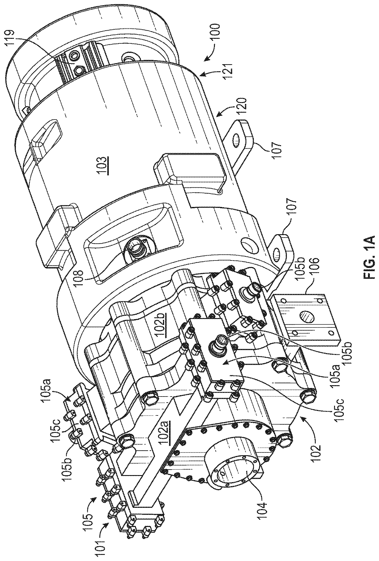
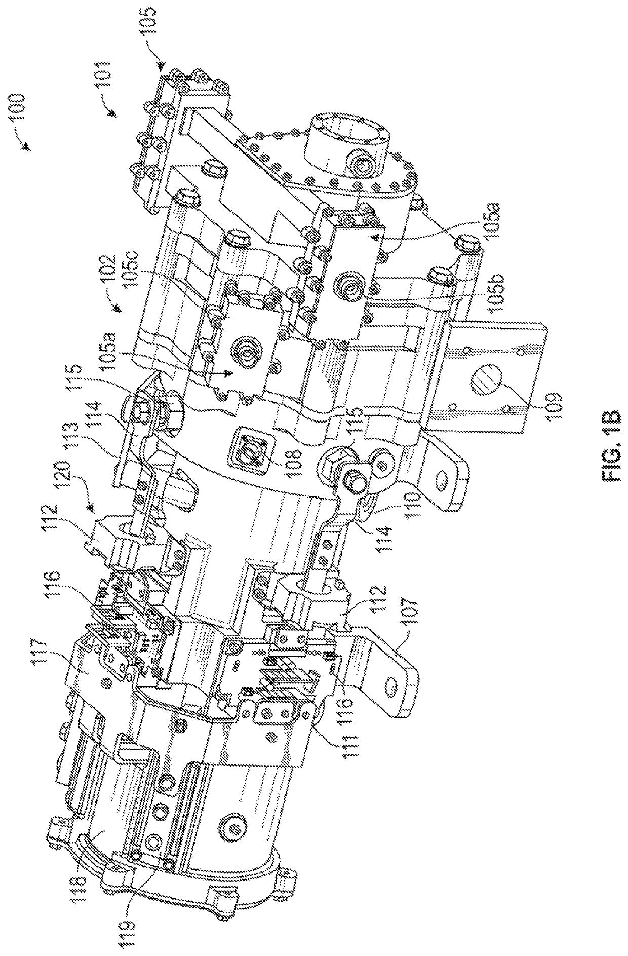
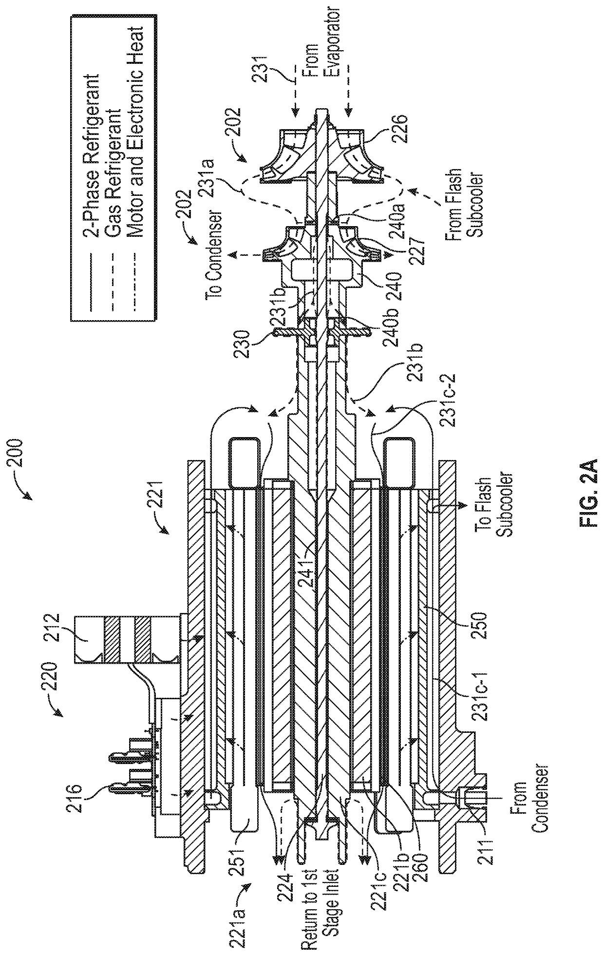
[0017]Broadly, the present invention provides components of a vapor cycle compressor into a single package. A two-stage centrifugal compressor is directly driven by a high-speed, brushless, permanent-magnet (PM) motor and a physically integrated motor ...


PUM


Abstract

A vapor cycle compressor includes a motor section and a compression section operatively engaged with the motor section. A refrigerant path is in the motor section and in the compression section. The refrigerant path includes: a compression refrigerant path, for a single phase compression refrigerant, in the compression section; an inner rotor shaft refrigerant path, for a single phase inner rotor shaft refrigerant, in the compression section and in the motor section; and a stator refrigerant path, for a two phase stator refrigerant, in the motor section.

Description

BACKGROUND OF THE INVENTION[0001]The present invention generally relates to vapor cycle compressors and, more particularly, to apparatus and methods of cooling associated components of vapor cycle compressors.[0002]Applications that require high power devices such as motors, compressors, fans, pumps, etc. produce large amounts of heat due to electrical losses. The heat generated is even greater when the controller losses are taken into account. In a typical aerospace application, the generated heat is conducted away by an independent fluid circuit at a high pressure and flow rate, and then dissipated to a lower temperature heat sink. However, the foregoing increases the complexity of a system and adds additional weight in the form of fluid and infrastructure.[0003]The concerns of weight and complexity are greater when system components are integrated into a single package. The concerns are further exacerbated when multiple fluids are used for heat transfer.[0004]As can be seen, ther...

Claims


Application Information

Patent Timeline
Patent Type & Authority Patents(United States)
IPC IPC(8): F04D29/58F04D17/12F25B31/00F25B1/04F04D29/057B64D13/06
CPCF04D29/584F04D17/122F04D29/5806F25B1/04F25B31/008B64D2013/0674F04D29/057B64D2013/0644F04D25/06F04D25/068F04D29/5813F05D2240/61F25B1/053F25B1/10F25B31/026F25B2400/13F25B2600/024F25B2600/0253F25B2700/151Y02T50/50
Inventor LEIGHTY, MICHAELMORITA, DENNIS MIKIOWHITE, STEPHEN L
Owner HONEYWELL INT INC
Why Eureka
Try Eureka