Bolt supply device

a supply device and bolt technology, applied in the direction of chutes, manufacturing tools, transportation and packaging, etc., can solve the problems of the above-mentioned bolt supply device without a mechanism and the vibration degrade the work environment, and achieve the effect of suppressing the degradation of the work environment and small in siz

Active Publication Date: 2021-11-09
TOYOTA JIDOSHA KK
View PDF12 Cites 3 Cited by
  • Summary
  • Abstract
  • Description
  • Claims
  • Application Information

AI Technical Summary

Benefits of technology

[0006]The disclosure has been made in order to solve such a problem and provides a bolt supply device that is small in size and suppresses the degradation of the work environment.
[0008]With this configuration, the bolt supply device makes it possible to cause the dropping speed of the bolt moving in the second groove to be higher than the dropping speed of the bolt moving in the first groove.
[0011]The bolt supply device according to the above-described aspect may further include a cover at the lower end of the third groove, the cover configured to restrict a movement of the bolt in a direction in which the head portion floats up. With this configuration, the bolt supply device can suppress a state in which the bolts dropping along the slide plate float up so that the flange portions of the adjacent bolts overlap each other.
[0012]According to the disclosure, it is possible to provide a bolt supply device that is small in size and suppresses the degradation of the work environment.

Problems solved by technology

The parts feeder described above is large in size, and further, the noise from the vibrator degrades the work environment.
On the other hand, the bolt supply device described above does not include a mechanism for automatically supplying the bolts.

Method used


Image

  • Bolt supply device
  • Bolt supply device
  • Bolt supply device

Examples


Embodiment Construction

[0036]The disclosure will be described below with reference to an embodiment of the disclosure, but this is not intended to limit the disclosure in the claims to the following embodiment. Further, all the configuration described in the embodiment is not necessarily essential as means for solving the problem. For clarification of description, the following description and the drawings are omitted or simplified as appropriate. In the respective drawings, the same signs are assigned to the same elements, and a duplicate description thereof is omitted as needed.

[0037]Outline of Bolt Supply Device

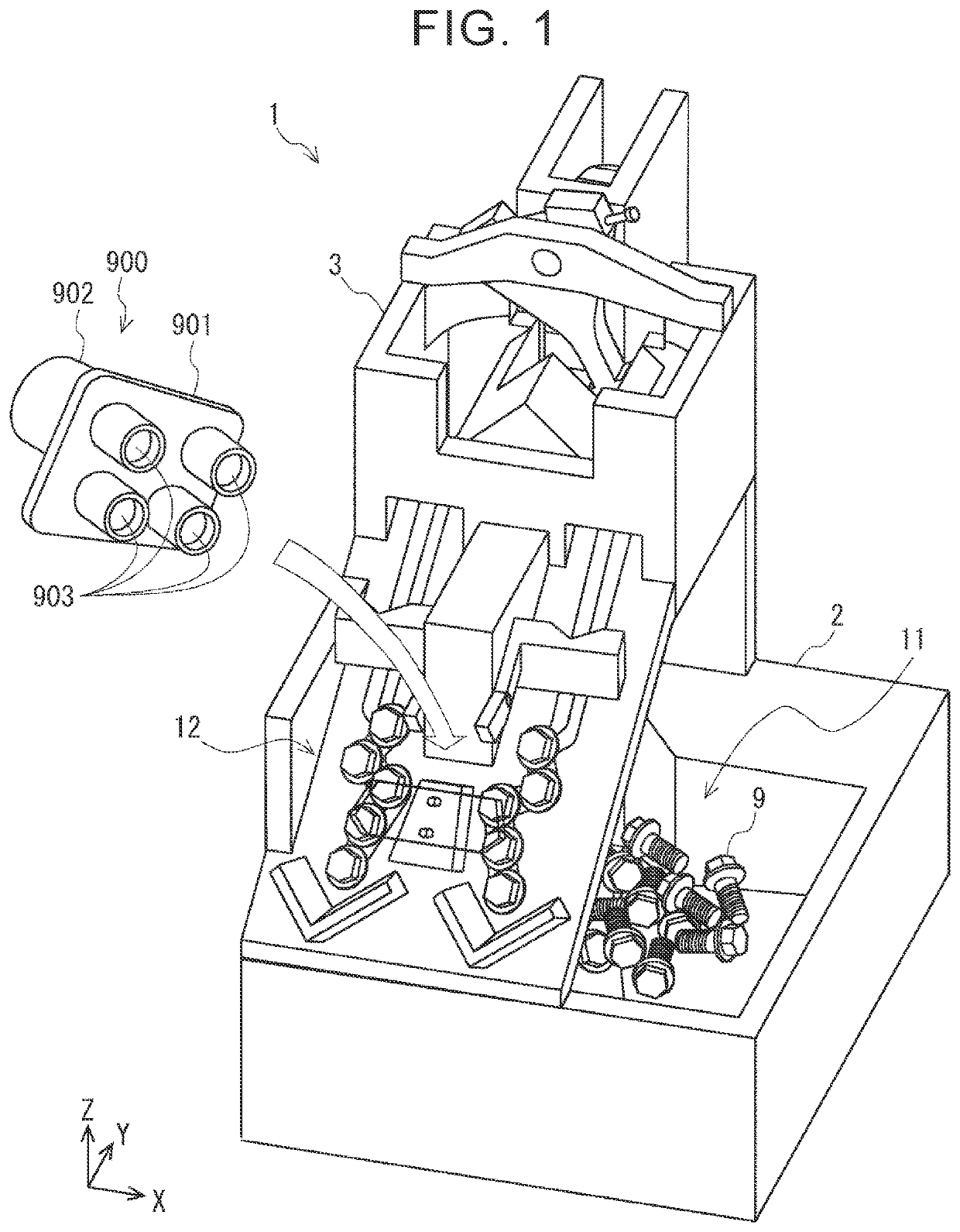
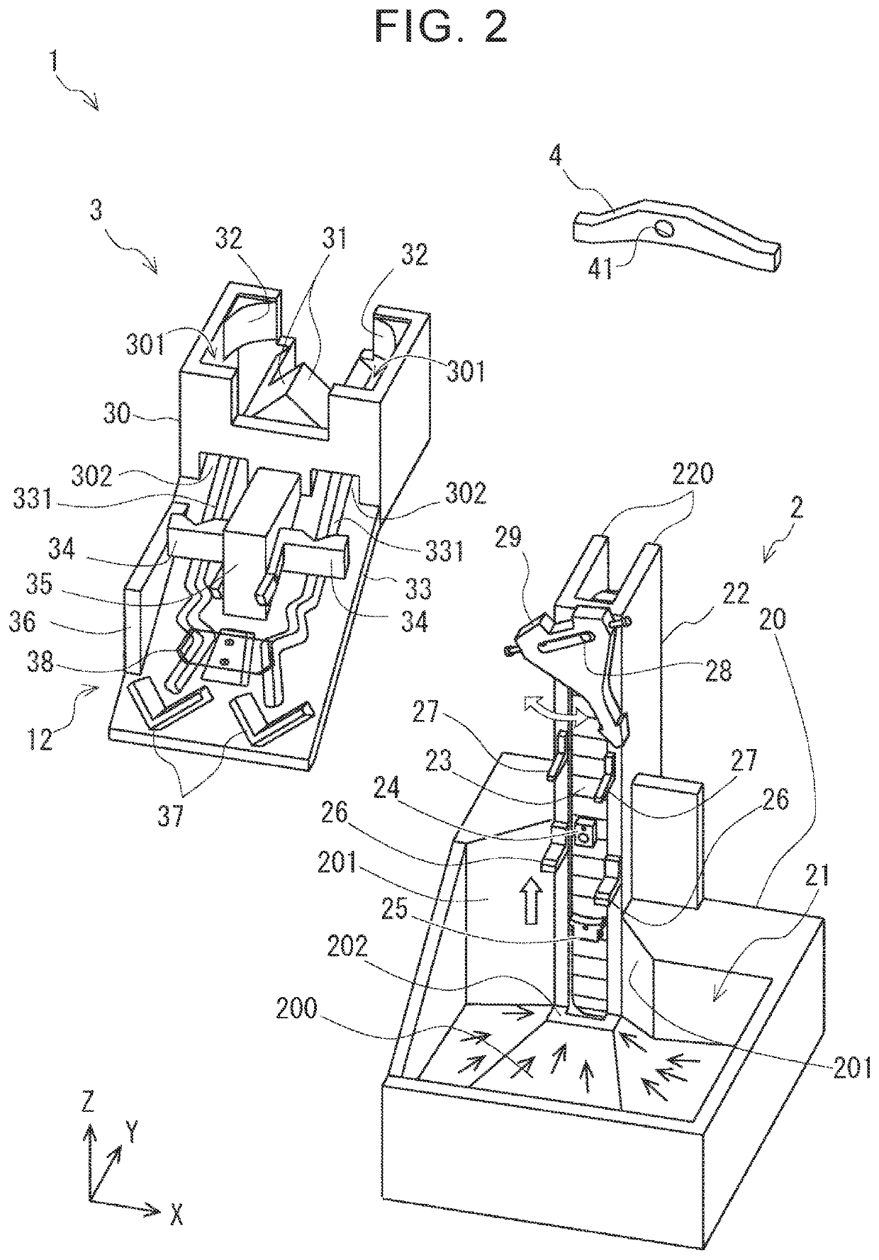
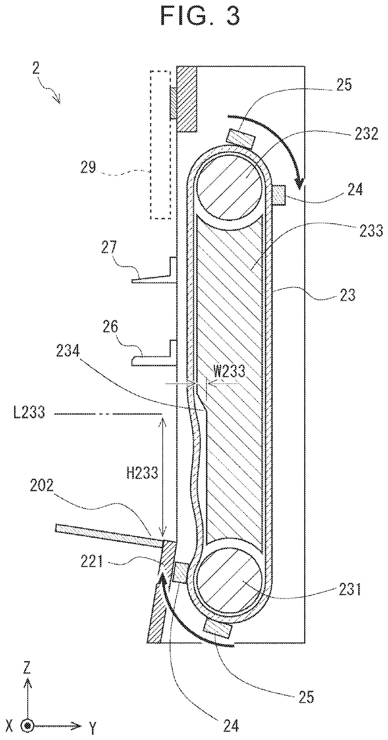
[0038]Hereinafter, the outline of a bolt supply device 1 according to an embodiment of the disclosure will be described. FIG. 1 is a schematic diagram of the bolt supply device 1 according to the embodiment. The bolt supply device 1 illustrated in FIG. 1 is in a state in which a plurality of thrown-in bolts is supplied to a predetermined position.

[0039]In FIG. 1, a right-handed orthogonal coordi...


PUM


Abstract

A bolt supply device includes a slide plate inclined to a vertical direction; and a groove portion formed in the slide plate and having a width that allows passing of a screw portion of a bolt and prevents passing of a flange portion of the bolt. The groove portion includes a first groove configured such that an angle formed between a line extending in an up-down direction along the slide plate and the first groove is a first angle; and a second groove connected to a lower end of the first groove and configured such that an angle formed between the line extending in the up-down direction along the slide plate and the second groove is a second angle smaller than the first angle. The bolt take-out portion is set in the groove portion at a lower end or below the lower end of the second groove.

Description

CROSS-REFERENCE TO RELATED APPLICATION[0001]This application claims priority to Japanese Patent Application No. 2020-027856 filed on Feb. 21, 2020, incorporated herein by reference in its entirety.BACKGROUND1. Technical Field[0002]The disclosure relates to a bolt supply device.2. Description of Related Art[0003]As a means to automatically supply bolts in the production line or the like, a device that aligns the bolts by a parts feeder including a vibrator is widely used. On the other hand, there has been developed a bolt supply device that has a structure small in size and not including a vibrator and aligns bolts at a predetermined position.[0004]For example, a bolt supply device described in Japanese Unexamined Patent Application Publication No. 2018-52661 (JP 2018-52661 A) includes a bolt throw-in portion into which bolts are thrown, a V-shaped guide disposed below the bolt throw-in portion, and a rotation promotion plate. The rotation promotion plate has an upper surface formed ...

Claims


Application Information

Patent Timeline
Patent Type & Authority Patents(United States)
IPC IPC(8): B65G11/08B25B23/04B65G1/08B65G47/14
CPCB65G11/081B25B23/04B65G1/08B65G11/086B65G47/1478B65G47/1492B65G47/248B65G15/58B23P19/002B65G47/1485B65G21/2018
Inventor KIRA, KAZUHIKO
Owner TOYOTA JIDOSHA KK
Why Eureka
Try Eureka