Disperser plates with intermeshing teeth and outer refining section

a technology of intermeshing teeth and disperser plates, applied in papermaking, textiles and papermaking, etc., can solve the problems of paper products, affecting the quality of paper products, so as to achieve the effect of adjusting the intensity and efficiency, reducing the load, and ensuring the quality of paper

Active Publication Date: 2021-11-16
ANDRITZ INC
View PDF20 Cites 0 Cited by
  • Summary
  • Abstract
  • Description
  • Claims
  • Application Information

AI Technical Summary

Benefits of technology

[0010]Applicant has discovered that there is potential to use dispersers to disperse and refine fibers to a desired quality while giving operators greater control over the amount of refining the fibers undergo in a single pass through an exemplary disperser comprising an exemplary disperser-refiner plate segment. The problem of having wasted time and energy resulting from the use of separate dispersion and refining apparatuses to produce recycled fibers of desired tensile strength is solved by adding a bar and groove refining section after (i.e. radially outward) of the intermeshing disperser teeth on a disperser plate segment, wherein the disperser teeth are taller than the refining bars relative to the back side of the exemplary disperser-refiner plate segment, and wherein the disperser teeth have sharp leading edges at the junction of sidewalls.
[0012]Applicant has found that intermeshing tooth designs of various geometries have the ability to apply energy levels of 20 kilowatt hour per ton (“kWh / T”) to 60 kWh / T generally, with some designs reaching 100 kWh / T levels and slightly above. Refining bar and groove designs have a much greater ability to apply energy because the gap between facing bar and groove regions can be controlled effectively to low values, such as a fraction of a millimeter. This results in load-ability of traditional refiner plates being multiple times higher than intermeshing tooth designs.
[0015]Without being bound by theory, a majority of the refining occurs in the fiber pad that accumulates in the gap between the opposing refining sections. The shear and compressive forces—particularly the compressive forces—of adjacent fibers moving past each other rapidly is thought to develop the fibers (i.e. to fray the fibrils that comprise the lamellae of the recycled paper fibers). The successively crossing bars and grooves of the opposing refining sections impart much of the shear and compressive forces into the fiber pad. For example, when two opposing bars cross each other, a fiber caught between these opposing bars can be thought to experience a higher load than when the opposing bars move past each other and two opposing grooves temporarily align. The average load is a function of the width of the refining gap. In the aggregate, by adjusting the width of the gap between the opposing refining sections, operators can adjust the load of the fiber pad between the opposing refining sections, and thereby adjust the intensity and efficiency with which the fiber is refined.
[0016]A disperser-refiner plate segment in accordance with the present disclosure includes an intermeshing section of concentric teeth, which is followed by a refining section using bars and grooves (i.e. the refining section is disposed radially outward of the intermeshing section of concentric teeth (i.e. the dispersion section)). In exemplary disperser-refiner plate segment designs, the gap between the intermeshing teeth of opposite discs may adjust by 0.1 mm to 0.4 mm for each millimeter of machine adjustment, whereas a bar and groove refining section will have a 1:1 gap adjustment with position change. That is, the design is conceived in such a way that the intermeshing section and the refining section will both be adjusted as the gap is controlled, but the effect on the refining section will be more pronounced. This difference may allow for a relatively unchanged dispersion effect while permitting greater control over the refining effect. As a result, when an operator adjusts the position of the plate assemblies relative to each other and thereby adjusts the operating gap between the exemplary disperser-refiner plate segments described herein, the operator can more precisely control the intensity of the refining energy being applied in the refining gap while also maintaining a fairly consistent dispersion energy applied to the fiber in the dispersion gap.
[0017]Consequently, the use of exemplary disperser-refiner plates with intermeshing teeth and an outer refining section may allow mill operators to improve dispersion efficiency, while also adding refining energy to the operator's pulp without using additional refining equipment or increasing the maximum amount of refining preformed on the fiber.

Problems solved by technology

This results in load-ability of traditional refiner plates being multiple times higher than intermeshing tooth designs.
Traditional bar and groove refiner plate segments have been used in the past in dispersers (i.e. the disperser machine) in lieu of disperser plates with some success, but such refiner plate segments normally have a lower dispersion efficiency and often will have limited throughput capacity.
The intermeshing tooth patterns lack the ability to apply substantial energy and therefore lack the ability to provide an increased refining effect.

Method used


Image

  • Disperser plates with intermeshing teeth and outer refining section
  • Disperser plates with intermeshing teeth and outer refining section
  • Disperser plates with intermeshing teeth and outer refining section

Examples


Embodiment Construction

[0023]The following detailed description of the preferred embodiments is presented only for illustrative and descriptive purposes and is not intended to be exhaustive or to limit the scope and spirit of the invention. The embodiments were selected and described to best explain the principles of the invention and its practical application. One of ordinary skill in the art will recognize that many variations can be made to the invention disclosed in this specification without departing from the scope and spirit of the invention.

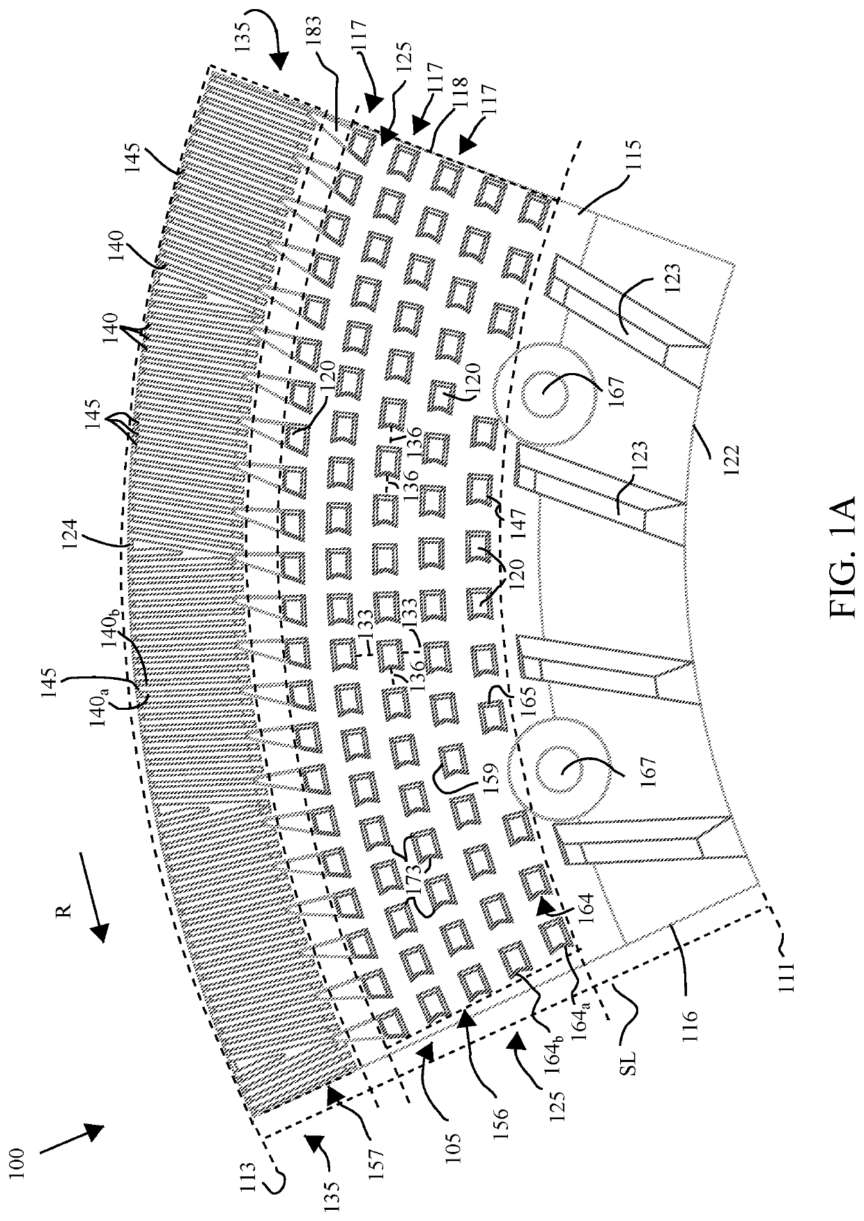
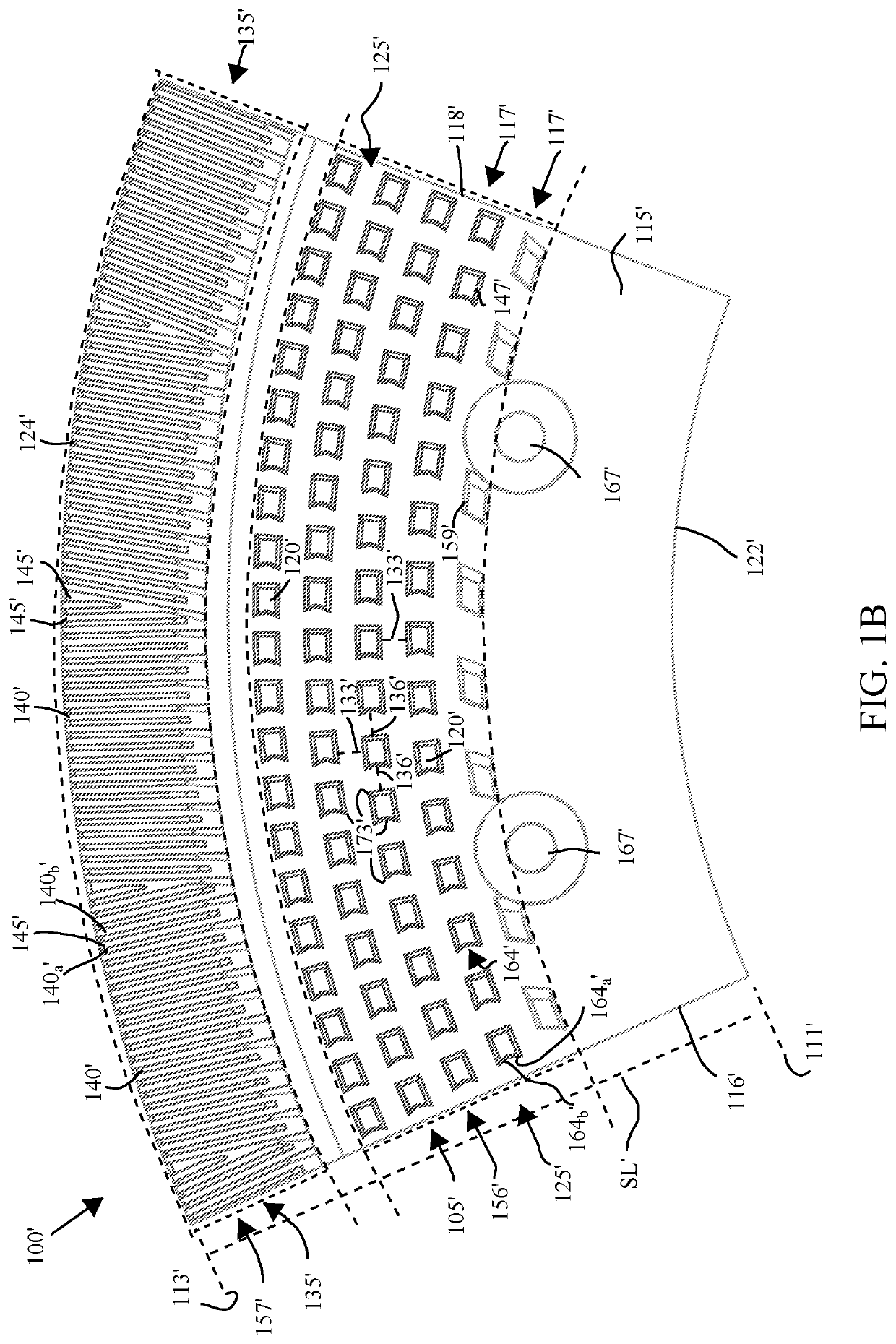
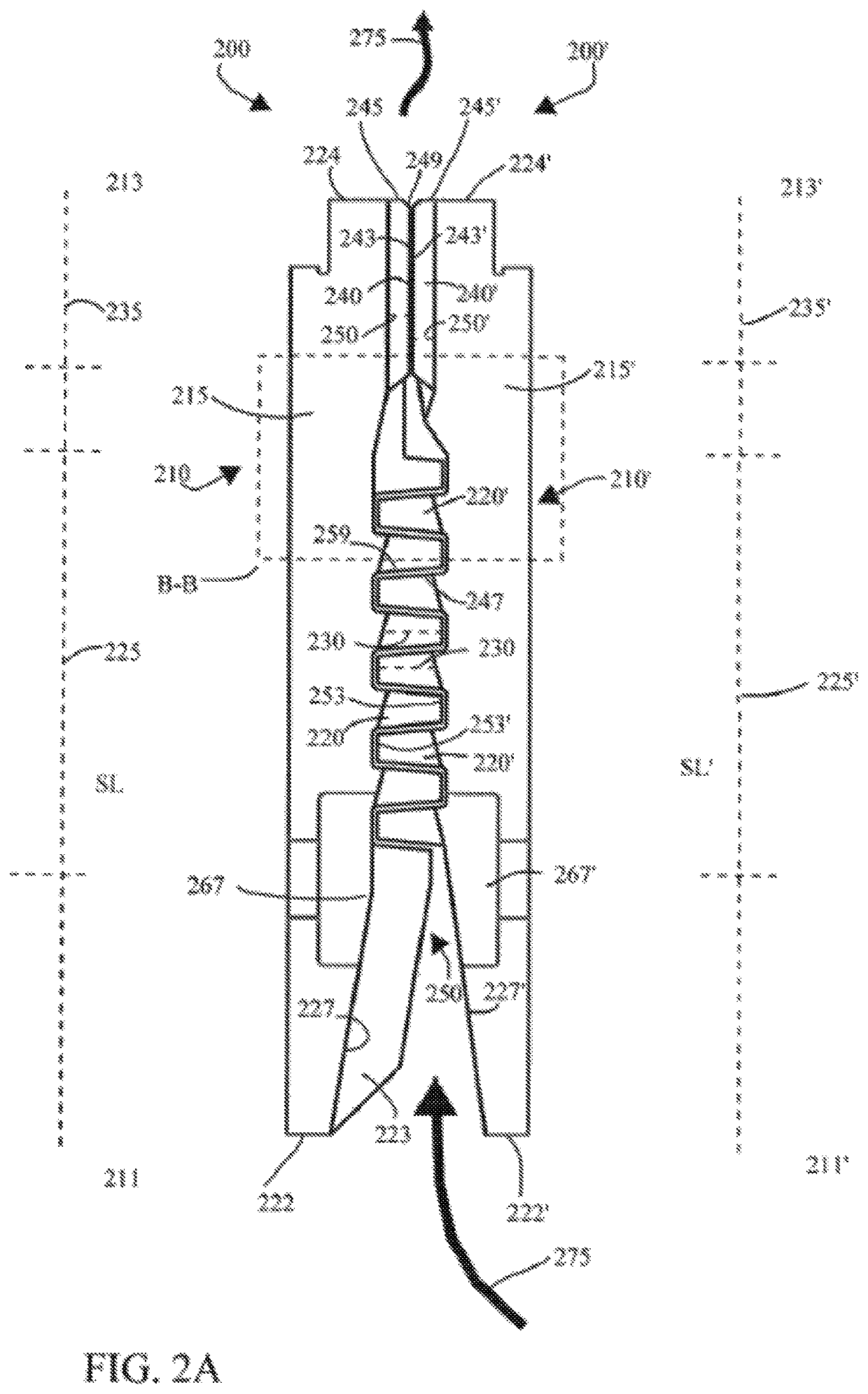
[0024]Similar reference characters indicate corresponding parts throughout the several views unless otherwise stated. Although the drawings represent embodiments of various features and components according to the present disclosure, the drawings are not necessarily to scale and certain features may be exaggerated in order to better illustrate embodiments of the present disclosure, and such exemplifications are not to be construed as limiting the scope of the p...


PUM

PropertyMeasurementUnit
lengthaaaaaaaaaa
lengthaaaaaaaaaa
lengthaaaaaaaaaa

Abstract

A disperser-refiner plate segment includes a refining section disposed radially outward from a dispersion section. Teeth in the dispersion section have a height that exceeds a height of refining bars in the refining section.

Description

RELATED APPLICATION[0001]This application claims the benefit under 35 U.S.C. § 119(e) to the provisional patent application having the Ser. No. 62 / 651,777 filed on Apr. 3, 2018, the entirety of which is incorporated herein by reference.BACKGROUND OF THE INVENTIONTechnical Field[0002]This disclosure relates generally to dispersers for the paper and board industry, and more particularly to disperser segments used to impart work onto recycled fiber.Related Art[0003]When recycling paper fibers, industrial recycling mill operators use dispersers to break down and separate contaminants in the paper fibers. People familiar with this process typically call these contaminants “stickies.” Stickies typically include glue, plastics, ink, and other such materials interspersed with the fibers being recycled. Operators can remove separated stickies from the fiber stock via screening, cleaning, and / or flotation processes. Any remaining particles can be broken down to such an extent that the stickie...

Claims


Application Information

Patent Timeline
Patent Type & Authority Patents(United States)
IPC IPC(8): D21D1/00B02C7/12D21C5/02D21D1/30
CPCD21D1/008B02C7/12D21C5/02D21D1/306Y02W30/64D21B1/026D21D1/20D21D1/303
Inventor GINGRAS, LUC
Owner ANDRITZ INC
Why Eureka
Try Eureka