Sensor arrangement and method of securing a monitored zone

a technology of sensors and monitored zones, applied in the direction of optical detection, measurement devices, electromagnetic wave reradiation, etc., can solve the problems of insufficient implementation of known securing concepts, too complex and dynamic, and in addition to protected fields, which do not permit any close cooperation with machines, etc., to achieve the effect of facilitating identification

Active Publication Date: 2021-11-16
SICK AG
View PDF15 Cites 1 Cited by
  • Summary
  • Abstract
  • Description
  • Claims
  • Application Information

AI Technical Summary

Benefits of technology

[0034]The control and evaluation unit is preferably configured to generate a hazard zone with respect to a detected object only at at least one specific position in the monitored zone. The specific position thus represents a kind of access lock. The identification only at specific positions can be associated with mobile machines that penetrate into the monitored zone at other points resulting in a safety-relevant response. Alternatively, the mo

Problems solved by technology

Protected fields in addition do not permit any close cooperation with machines, in particular with robots (HRC, human robot collaboration).
This would be too complex and too dynamic and a sufficient safety distance from future machine positions should also be observed.
Such approaches have, however, not yet been satisfactorily implemented in known securing concepts.
The accessibility of the plant and the cooperation between the worker and the machine remain substantially restricted.
A large production area is therefore still required and the increase in flexibility sought is not achieved.
However, DE 10 2004 038 906 B4 relates to a light grid that is already not suitable for a flexible monitoring using human robot collaboration.
However, the described disadvantages of a light grid remain.
A person would, however, actually not be permitted to approach as desired so that this concept cannot be transferred to a close human robot collaboration.
Apart from this, it would also be exceptionally difficult to identify a person on the basis of a contour with a reliability that satisfies the demands of a safety engineering application.
The respective calculation of the protected fields is complex, particularly when

Method used


Image

  • Sensor arrangement and method of securing a monitored zone
  • Sensor arrangement and method of securing a monitored zone
  • Sensor arrangement and method of securing a monitored zone

Examples


Embodiment Construction

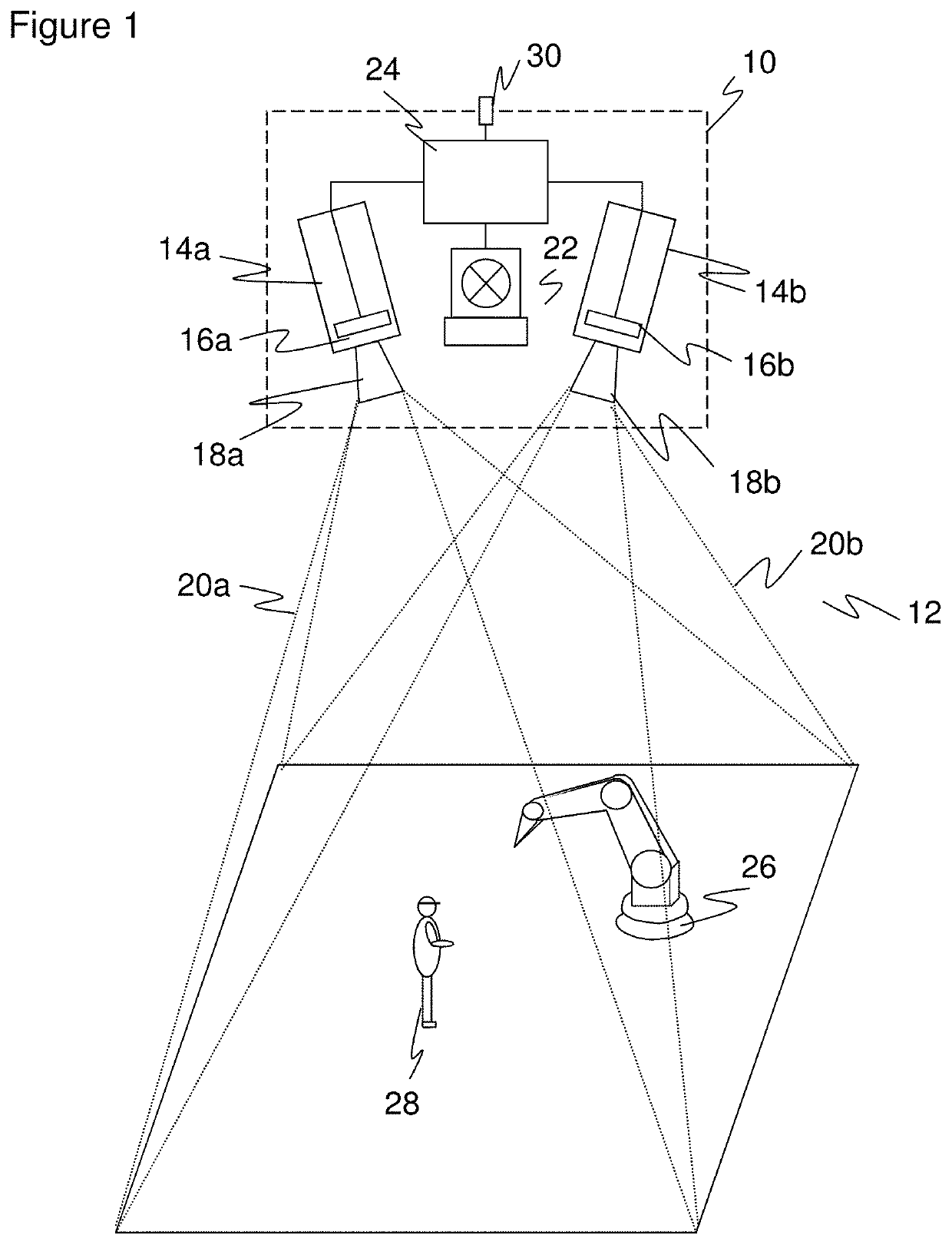
[0045]FIG. 1 shows the general design of a stereo camera for recording a depth map in a schematic three-dimensional representation. The stereo camera is only one example for a monitoring sensor 10 with respect to which the object detection will be explained in the particularly advantageous case of a three-dimensional spatial monitoring. The other 3D cameras mentioned in the introduction would equally be conceivable and, as a further alternative, other optoelectronic sensors such as 2D cameras or laser scanners.

[0046]Two camera modules 14a, 14b are mounted at a known fixed distance from one another for the detection of a monitored zone or spatial zone 12 and each take images of the spatial zone 12. An image sensor 16a, 16b, usually a matrix-type reading chip, is provided in each camera module 14a, 14b and records a rectangular pixel image, for example a CCD or a CMOS sensor. The two image sensors 16a, 16b together form a 3D image sensor or light receiver for detecting a depth map. On...


PUM


Abstract

A sensor arrangement for securing a monitored zone having at least one hazard zone with respect to a machine is provided, wherein the sensor arrangement has at least one optoelectronic monitoring sensor for detecting objects in the monitored zone and has a control and evaluation unit that is configured to compare the positions of detected objects with the hazard zone and to initiate a safety-relevant response of the machine in the case of a dangerous position. The control and evaluation unit is furthermore configured to generate and to monitor a further hazard zone with respect to a detected object.

Description

BACKGROUND1. Field[0001]The invention relates to a sensor arrangement for securing a monitored zone having at least one hazard zone with respect to a machine, wherein the sensor arrangement has at least one optoelectronic monitoring sensor for detecting objects in the monitored zone and has a control and evaluation unit that is configured to compare the positions of detected objects with the hazard zone and to initiate a safety-relevant response of the machine in the case of a dangerous position. The invention further relates to a method of securing a monitored zone having at least one hazard zone with respect to a machine, wherein objects are detected in the monitored zone and the positions of detected objects are compared with the hazard zone to initiate a safety-relevant response of the machine in the case of a dangerous position.2. Description of the Related Art[0002]The primary goal of safety engineering is to protect persons from hazard sources such as, for example, machines i...

Claims


Application Information

Patent Timeline
IPC IPC(8): F16P3/14G01V8/20
CPCF16P3/142F16P3/144G01V8/20G01S17/06
Inventor BÖHNING, MARKUSDRUZELLA, ULRICHSCHUBERT, LARSSTEINKEMPER, HEIKO
Owner SICK AG
Why Eureka
Try Eureka