
Fishing line rigging tool

a technology for fishing line and rigging rods, which is applied in the field of fishing tackle, can solve the problems of increasing difficulty in rigging, time-consuming, tedious and frustrating, and irritating, and achieve the effect of facilitating compression and expansion and facilitating transverse wedging of the lin

Active Publication Date: 2021-11-23
WILCOXON JOHN L +1
View PDF13 Cites 1 Cited by
  • Summary
  • Abstract
  • Description
  • Claims
  • Application Information

AI Technical Summary

Benefits of technology

The invention is a tool that helps feed fishing line through a fishing rod's eyelets. It has a curved guide that can fit through each eyelet with a loop of filament attached. The loop is twisted so that it forms a figure-eight shape, with a wider and narrower part. The wider part allows for easier insertion of the fishing line, while the overlap allows the line to pass through from the wider to narrower part. The loop is flexible to adjust to the line passing through and the eyelet. This tool makes it easier and more efficient to fish with.

Problems solved by technology

Rigging a fishing line through the eyelets of a fishing rod, and sometimes multiple fishing rods, can be time-consuming, tedious and frustrating, especially if hand-eye coordination is hampered by physical, spacial, climatic or other limitations.
For example, arthritis, less than twenty-twenty vision, tight or obstructed quarters on shore or in a boat and turbulent waters are just a few of the conditions which, alone or in concert, can make rigging increasingly difficult.
Lost time re-rigging lines which have been damaged, broken or intentionally cut because of age, crimps, snags, tangles, propellers and the like can be particularly irritating if the fish are biting at an accelerated frequency for a likely short period of time.

Method used


Image

  • Fishing line rigging tool
  • Fishing line rigging tool
  • Fishing line rigging tool

Examples


Embodiment Construction

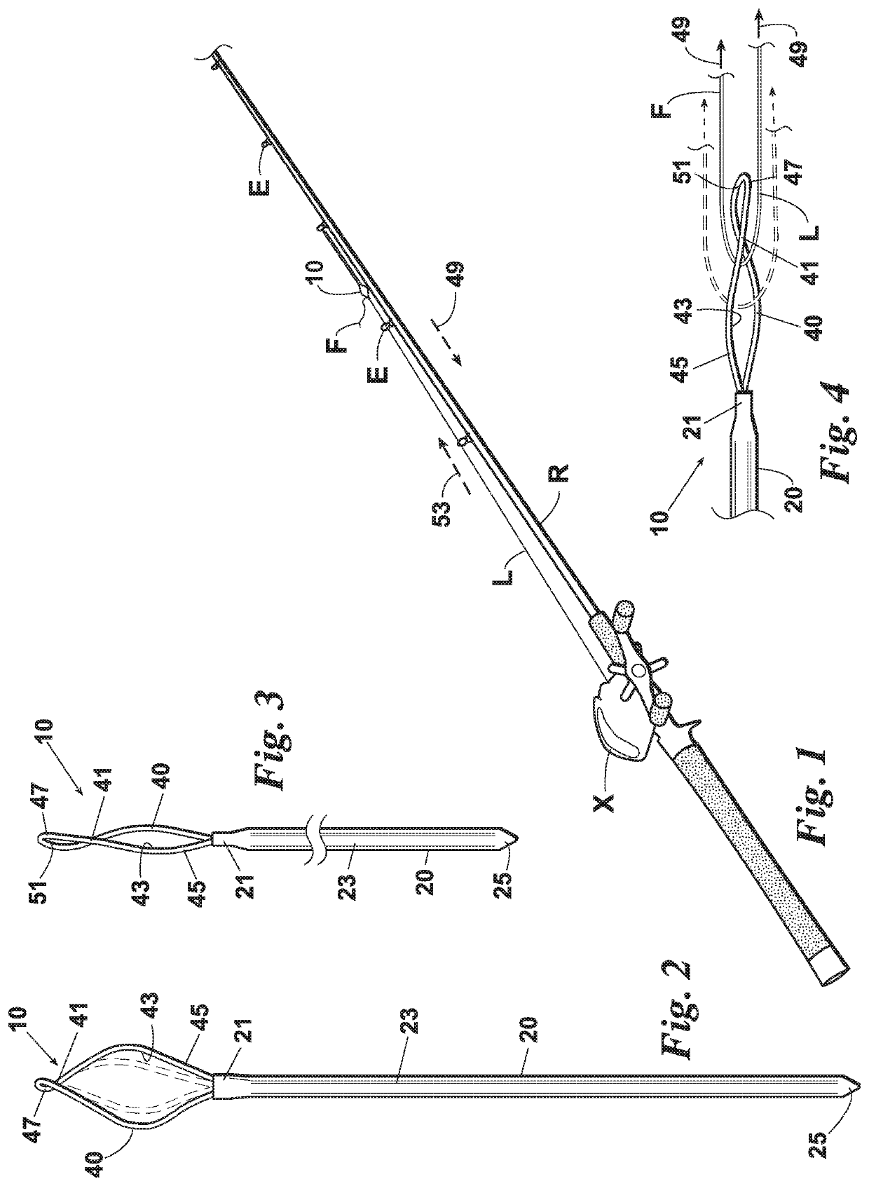
[0018]Turning to FIG. 1, a tool 10 in accordance with the invention is useful for feeding a fishing line L through the eyelets E of a fishing rod R.

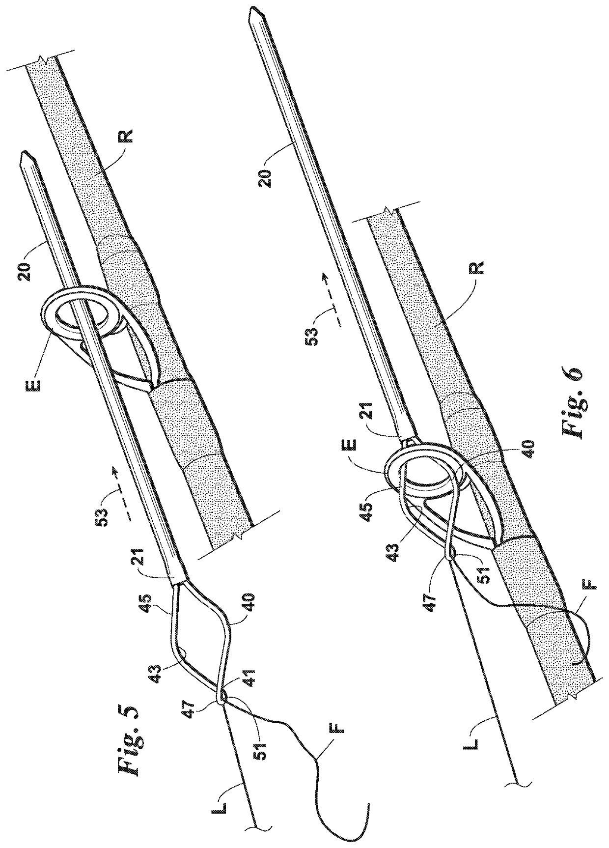
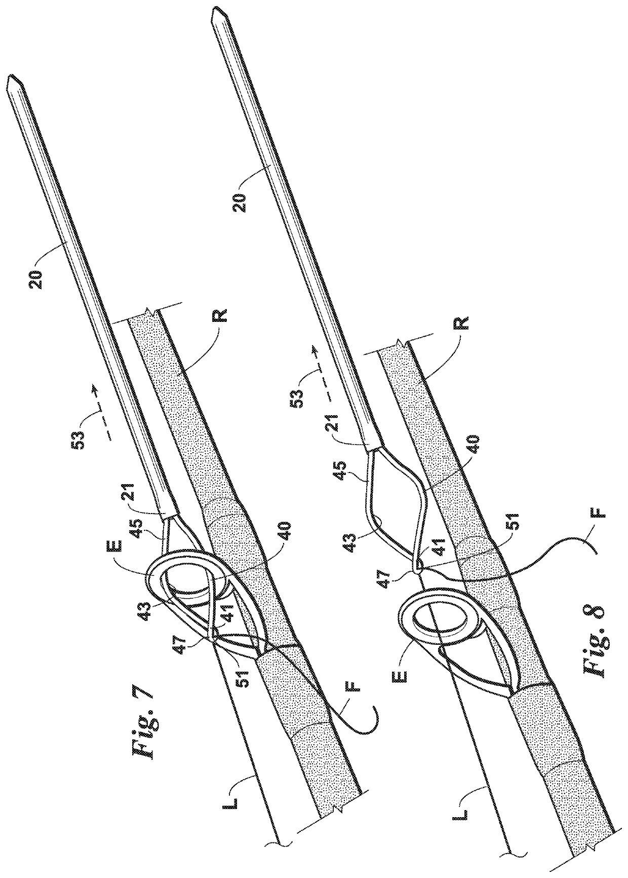
[0019]Looking at FIGS. 2-3, the tool 10 has an elongated guide 20 contoured to pass through each of the eyelets E. A loop of filament 40 is attached to a trailing end 21 of the guide 20. Comparing FIGS. 1 and 2, the loop 40 is twisted across itself at a distal overlap 41 to form an elongated figure-eight 43 with a proximal portion 45 wider and a distal portion 47 narrower than each of the eyelets E. However, comparing FIGS. 1 and 3, the width of the proximal portion 45 can be compressed to pass through the smallest eyelet E of the rod R. As seen in FIG. 3, in the compressed condition, the distal portion 47 is lengthened as the overlap 41 shifts in the proximal direction.

[0020]As seen in FIG. 4, the wider proximal portion 45 of the figure-eight 43 permits easier insertion of a free end F of the fishing line L into the loop 40 of the tool ...


PUM


Abstract

A tool for feeding a fishing line through the eyelets of a fishing rod has a loop of filament attached to an elongated guide and twisted across itself at a distal overlap to form a figure-eight with proximal and distal portions wider and narrower, respectively, than the eyelets. The wider portion facilitates insertion of a free end of the line into the loop. The loop is resiliently flexible so that the overlap separates and then recovers as the inserted line is passed transversely through the gap into the narrower portion of the figure-eight. The passed line is then transversely wedged in the narrower portion of the figure-eight. The loop is also resiliently flexible so that, as the guide leads the loop and the line through each eyelet, the wider portion of the loop compresses and then expands, inhibiting inadvertent withdrawal of the tool from an eyelet.

Description

BACKGROUND OF THE INVENTION[0001]This invention relates generally to fishing tackle and more particularly concerns tools for rigging a fishing rod.[0002]Fishing rod eyelets are relatively small and are usually sequentially smaller from reel to rod tip. Rigging a fishing line through the eyelets of a fishing rod, and sometimes multiple fishing rods, can be time-consuming, tedious and frustrating, especially if hand-eye coordination is hampered by physical, spacial, climatic or other limitations. For example, arthritis, less than twenty-twenty vision, tight or obstructed quarters on shore or in a boat and turbulent waters are just a few of the conditions which, alone or in concert, can make rigging increasingly difficult. Lost time re-rigging lines which have been damaged, broken or intentionally cut because of age, crimps, snags, tangles, propellers and the like can be particularly irritating if the fish are biting at an accelerated frequency for a likely short period of time.[0003]I...

Claims


Application Information

Patent Timeline
Patent Type & Authority Patents(United States)
IPC IPC(8): A01K97/00A01K87/04A01K87/00A01K91/03
CPCA01K97/00A01K87/04A01K87/00A01K87/002A01K91/03
Inventor WILCOXON, JOHN L.LATTIMER, BRANDON K.
Owner WILCOXON JOHN L
Learn More