Rotor blade with noise reduction means

a technology of noise reduction and rotor blade, which is applied in the direction of wind energy generation, mechanical equipment, machines/engines, etc., can solve the problems of canopy self-noise at higher frequencies, silent about any application of the disclosed theoretical analysis, and the proportion of onshore wind turbines running at reduced power

Active Publication Date: 2021-11-23
SIEMENS GAMESA RENEWABLE ENERGY AS
View PDF19 Cites 2 Cited by
  • Summary
  • Abstract
  • Description
  • Claims
  • Application Information

AI Technical Summary

Benefits of technology

[0014]The cited study of Clark et al. could be interpreted in a way that noise which is produced by an airflow flowing along a rough surface can be reduced significantly by an owl inspired porous canopy in the turbulent boundary layer. The roughness noise is in this case generated by roughness elements, which scatter the unsteady pressure fluctuations beneath the turbulent boundary layer into sound. The canopy may reduce the unsteady surface pressures drastically, and as a result, the far field noise may be reduced.
[0067]Note that in order to prevent clogging, streamwise fibers are more advantageous than a porous surface with small openings. Cross stream fibers have the advantage to crack off dirt automatically due to vibrations.

Problems solved by technology

A substantial portion of onshore wind turbines are actually running at reduced power due to noise constraints at least during certain time periods.
For large wind turbines which comprise rotor blades with a length exceeding 40 meters, a dominant noise source is trailing edge noise from the outer part of the rotor blades.
Another important noise source is leading edge noise that is generated by turbulences at the leading edge section of the rotor blade.
However, the cited article is silent about any applications of the disclosed theoretical analysis.
The canopy may produce self-noise at higher frequencies.
More specifically, a significant share of the noise is generated at the trailing edge of the trailing edge section.
The drawback of potentially increased aerodynamic effect may be acceptable if, for instance, the airflow is guided such that interaction of the airflow and the connection means or device is minimal anyway.

Method used


Image

  • Rotor blade with noise reduction means
  • Rotor blade with noise reduction means
  • Rotor blade with noise reduction means

Examples


first embodiment

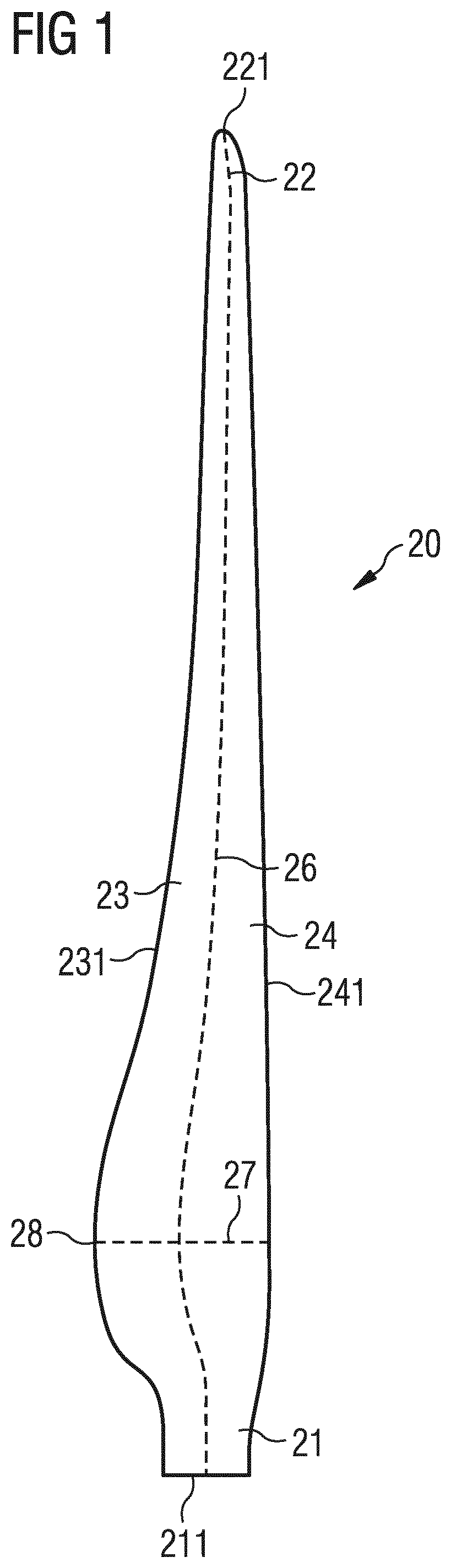
[0090]FIG. 2 shows a perspective view of a rotor blade 20 with a noise reduction means or device 40. The rotor blade 20 comprises a suction side 252 and a pressure side 251. Furthermore, it comprises a leading edge 241 and a trailing edge 231. Airflow 31 flows along the surfaces 32 of the rotor blade 20. In the example shown in FIG. 2, the airflow impinges at the leading edge section 24 of the rotor blade 20 in a direction that is parallel to the chord line 27 of the rotor blade 20.

[0091]The airflow 31 is separated into an upper airflow 312 and a lower airflow 313. The upper airflow 312 flows along the suction side 252 of the rotor blade and the lower airflow 313 flows along the pressure side 251 of the rotor blade. Downstream of the trailing edge 231, the upper airflow 312 and the lower airflow 313 reunite together.

[0092]The noise reduction means or device 40 comprises a cover 41 and connection means or device by which the cover 41 is connected to the surface 32 of the rotor blade ...

second embodiment

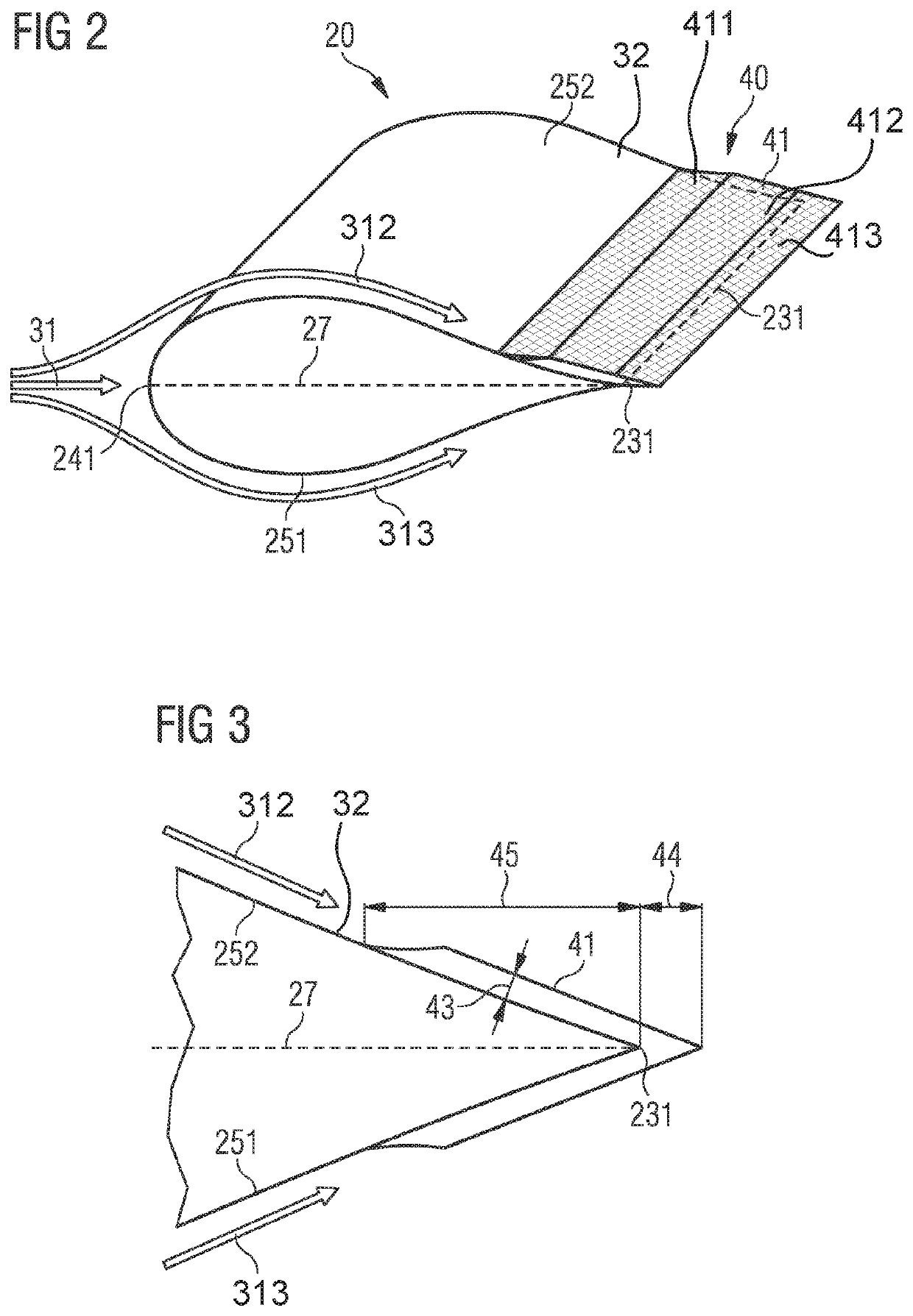
[0094]FIG. 3 shows a noise reduction means or device 40 in a cross-sectional view. Again, the suction side 252 and the pressure side 251 are depicted. The cover 41 is arranged in a predetermined distance 43 with regard to the surface 32 of the rotor blade. An extension of the middle part 412 of the cover 41 downstream of the trailing edge 44, i.e. a downstream part 413, and an extension of the cover 41 upstream of the trailing edge 45, i.e. an upstream part 411, can be seen. Note the smooth transition that the cover 41 is following between the surface 32 of the rotor blade 20 upstream of the trailing edge 231 and the equal and constant part of the cover 41 with regard to the surface of the rotor blade.

[0095]FIG. 4 shows an embodiment of a noise reduction means or device 40 similar to the second embodiment. Here, the connection means or device 42 are explicitly illustrated. FIG. 4 also illustrates the boundary layer 33 and a velocity profile 311 of the airflow 31. The lengths of the ...

third embodiment

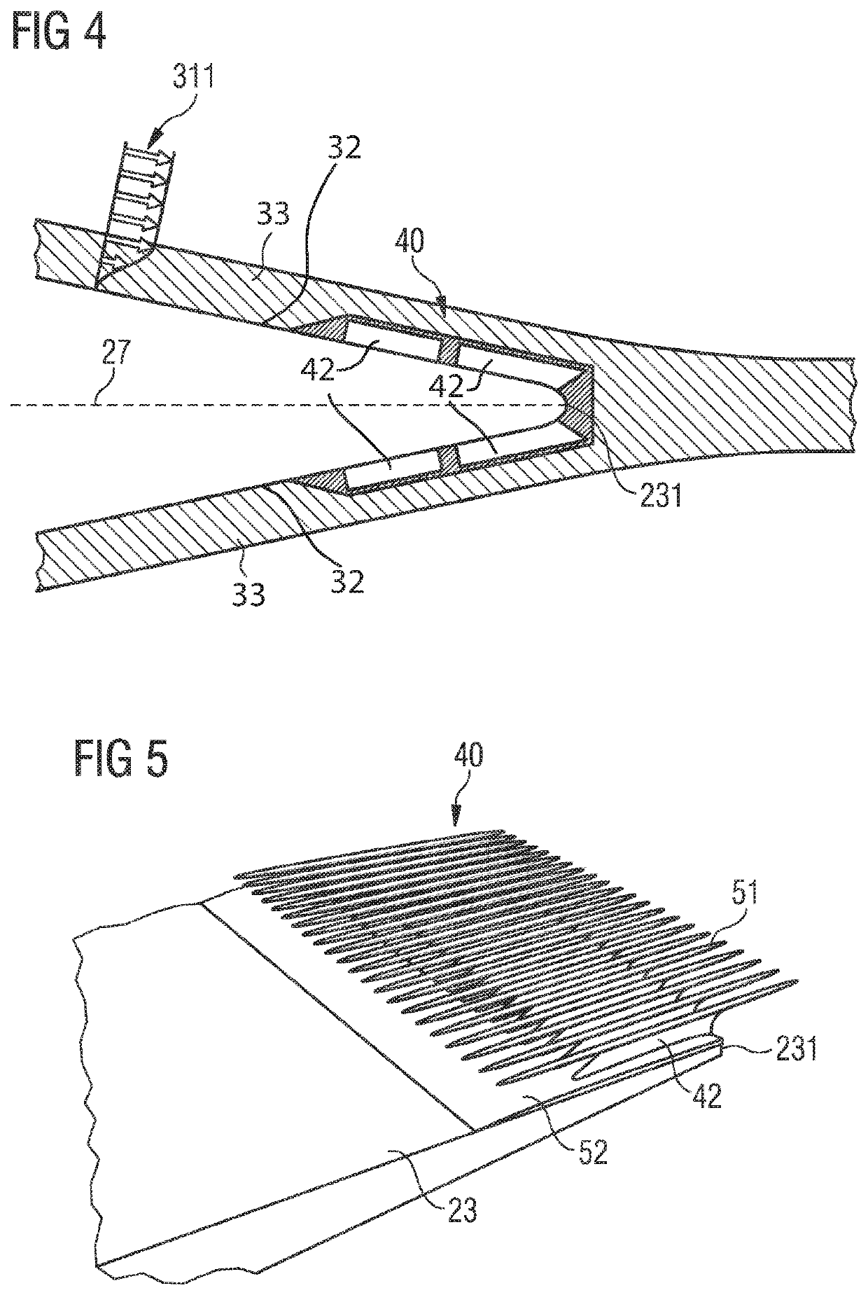
[0097]The third embodiment is also referred as the “comb embodiment” or “needles embodiment”. This is due to the fact that the cover 41 is realized by a set of bars 51 which are arranged substantially parallel to each other. The bars 51 are connected via connection means or device 42 to the surface 32 of the rotor blade. In particular, the connection means or device 42 directly connect with a connection plate 52. The connection plate 52 is then connected with the surface 32 of the rotor blade.

[0098]This is advantageous as the connection means or device 42 can separately be attached to the connection plate 52 and the connection plate 52 as a whole can be attached to the surface 32 of the rotor blade. The bars 51 comprise a predetermined distance 43 of a few millimeters to a few centimeters between the cover and the surface 32 of the rotor blade. Also note that the bars 51 partially extend downstream of the trailing edge 231.


PUM

PropertyMeasurementUnit
distanceaaaaaaaaaa
distanceaaaaaaaaaa
lengthaaaaaaaaaa

Abstract

A rotor blade for a wind turbine is provided. The rotor blade includes a pressure side, a suction side, a leading edge section with a leading edge, and a trailing edge section with a trailing edge. An airflow flows along the surface of the rotor blade from the leading edge section to the trailing edge section and builds up a boundary layer in close proximity to the surface of the rotor blade. The rotor blade includes a noise reduction device for reducing noise which is generated by interaction of the airflow and the rotor blade. The noise reduction device is located within the boundary layer of the rotor blade. The noise reduction device includes a cover and connection device for connecting the cover to the surface of the rotor blade. The cover spans at least over a part of the surface of the rotor blade.

Description

CROSS-REFERENCE TO RELATED APPLICATIONS[0001]This application claims priority to PCT Application No. PCT / EP2014 / 066406, having a filing date of Jul. 30, 2014, based off of EP Application No. 14172977.2 having a filing date of Jun. 18, 2014, the entire contents of which are hereby incorporated by reference.FIELD OF TECHNOLOGY[0002]The following relates to a rotor blade for a wind turbine. Specifically, the invention relates to a rotor blade with a noise reduction means or device for reducing noise which is generated by interaction of the airflow and the rotor blade.BACKGROUND[0003]Noise which is arising from rotor blades of wind turbines is a critical factor when it comes to obtaining a permission to erect a wind turbine. This is particularly the case if wind turbines shall be erected close to residential areas.[0004]Wind turbines may be deliberately operated at reduced power in order to meet noise constraints. A substantial portion of onshore wind turbines are actually running at re...

Claims


Application Information

Patent Timeline
Patent Type & Authority Patents(United States)
IPC IPC(8): F03D1/06
CPCF03D1/0675F03D1/06F03D1/0633F05B2240/221F05B2240/32F05B2260/96F05B2280/6012F05B2280/6013Y02E10/72
Inventor ASHEIM, MICHAEL J.DICKOW, KRISTOFFER AHRENSENEVOLDSEN, PEDER BAYLOEVEN, ALEXLORENZONI, VALERIOOERLEMANS, STEFANOLSEN, ANDERS SMAERUPRICHERT, BODOSINGH, MANJINDER J.TORGARD, SIGMUND WENNINGSTED
Owner SIEMENS GAMESA RENEWABLE ENERGY AS
Why Eureka
Try Eureka