Rotor blade with noise reduction means
a technology of noise reduction and wind turbine, which is applied in the direction of wind energy generation, mechanical equipment, machines/engines, etc., can solve the problems of canopy self-noise at higher frequencies, reduce the stability and robustness of noise reduction, and silent about any application of disclosed theoretical analysis. , to achieve the effect of reducing the number of wind turbines
- Summary
- Abstract
- Description
- Claims
- Application Information
AI Technical Summary
Benefits of technology
Problems solved by technology
Method used
Image
Examples
first embodiment
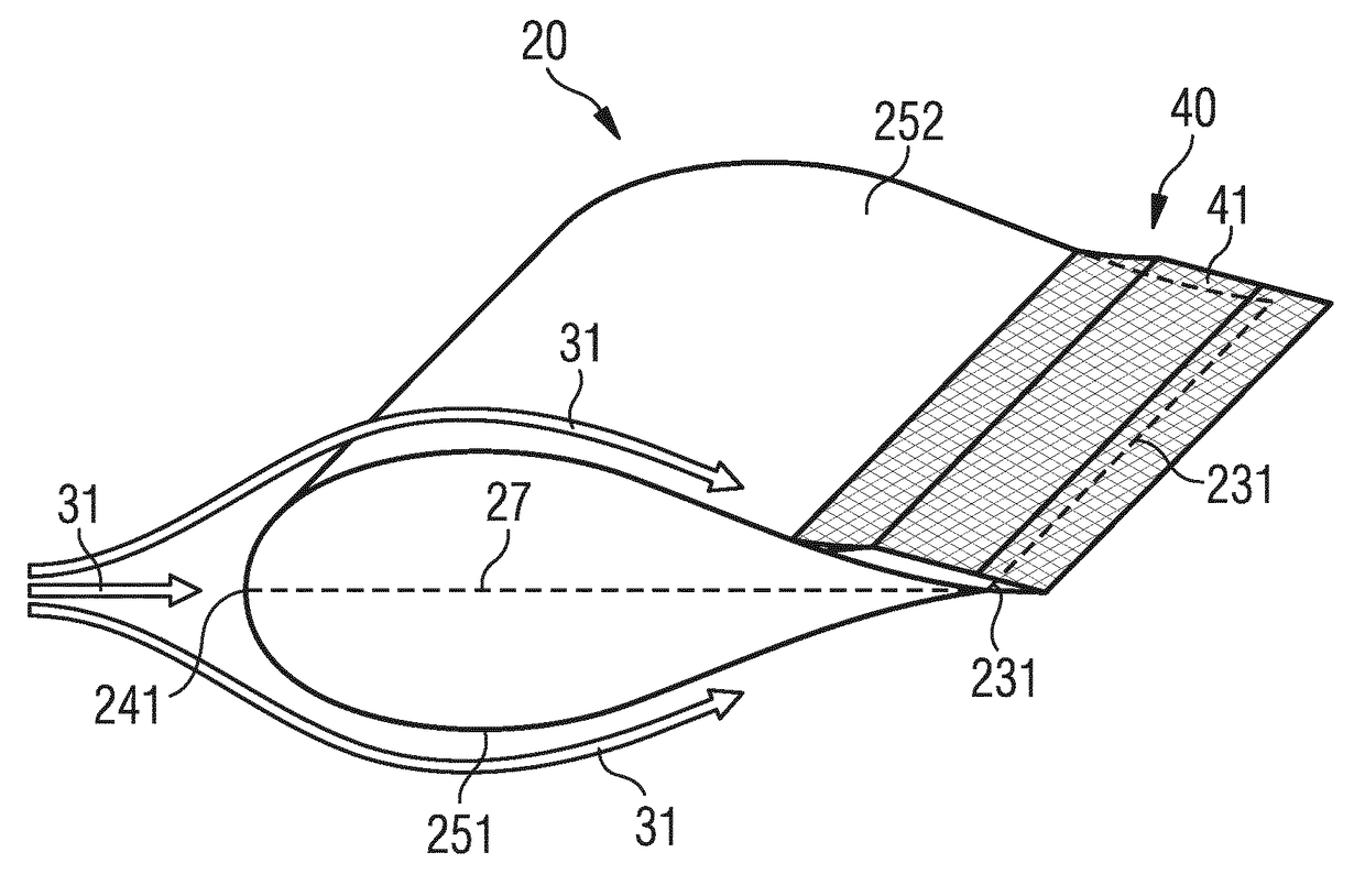
[0090]FIG. 2 shows a perspective view of a rotor blade 20 with a noise reduction means or device 40. The rotor blade 20 comprises a suction side 252 and a pressure side 251. Furthermore, it comprises a leading edge 241 and a trailing edge 231. Airflow 31 flows along the surfaces 32 of the rotor blade 20. In the example shown in FIG. 2, the airflow impinges at the leading edge section 24 of the rotor blade 20 in a direction that is parallel to the chord line 27 of the rotor blade 20.
[0091]The airflow 31 is separated into an upper airflow 312 and a lower airflow 313. The upper airflow 312 flows along the suction side 252 of the rotor blade and the lower airflow 313 flows along the pressure side 251 of the rotor blade. Downstream of the trailing edge 231, the upper airflow 312 and the lower airflow 330 reunite together.
[0092]The noise reduction means or device 40 comprises a cover 41 and connection means or device by which the cover 41 is connected to the surface 32 of the rotor blade ...
second embodiment
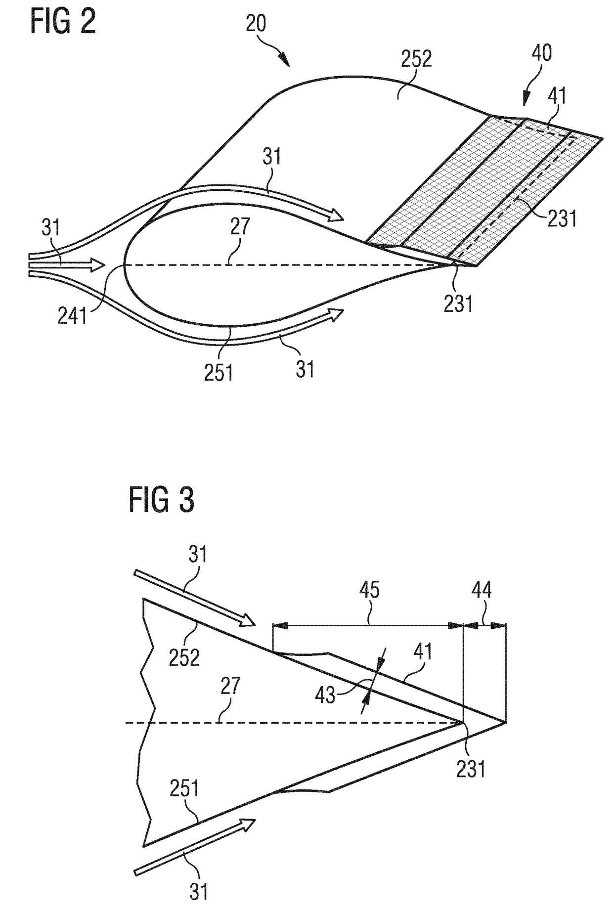
[0094]FIG. 3 shows a noise reduction means or device 40 in a cross-sectional view. Again, the suction side 252 and the pressure side 251 are depicted. The cover 41 is arranged in a predetermined distance 43 with regard to the surface 32 of the rotor blade. An extension of the middle part 412 of the cover 41 downstream of the trailing edge 44, i.e. a downstream part 413, and an extension of the cover 41 upstream of the trailing edge 45, i.e. an upstream part 411, can be seen. Note the smooth transition that the cover 41 is following between the surface 32 of the rotor blade 20 upstream of the trailing edge 231 and the equal and constant part of the cover 41 with regard to the surface of the rotor blade.
[0095]FIG. 4 shows an embodiment of a noise reduction means or device 40 similar to the second embodiment. Here, the connection means or device 42 are explicitly illustrated. FIG. 4 also illustrates the boundary layer 33 and a velocity profile 311 of the airflow 31. The lengths of the ...
third embodiment
[0097]The third embodiment is also referred as the “comb embodiment” or “needles embodiment”. This is due to the fact that the cover 41 is realized by a set of bars 51 which are arranged substantially parallel to each other. The bars 51 are connected via connection means or device 42 to the surface 32 of the rotor blade. In particular, the connection means or device 42 directly connect with a connection plate 52. The connection plate 52 is then connected with the surface 32 of the rotor blade.
[0098]This is advantageous as the connection means or device 42 can separately be attached to the connection plate 52 and the connection plate 52 as a whole can be attached to the surface 32 of the rotor blade. The bars 51 comprise a predetermined distance 43 of a few millimeters to a few centimeters between the cover and the surface 32 of the rotor blade. Also note that the bars 51 partially extend downstream of the trailing edge 231.
PUM
| Property | Measurement | Unit |
|---|---|---|
| distance | aaaaa | aaaaa |
| distance | aaaaa | aaaaa |
| length | aaaaa | aaaaa |
Abstract
Description
Claims
Application Information
 - R&D
- Intellectual Property
- Life Sciences
- Materials
- Tech Scout
- Unparalleled Data Quality
- Higher Quality Content
- 60% Fewer Hallucinations
Browse by: Latest US Patents, China's latest patents, Technical Efficacy Thesaurus, Application Domain, Technology Topic, Popular Technical Reports.
© 2025 PatSnap. All rights reserved.Legal|Privacy policy|Modern Slavery Act Transparency Statement|Sitemap|About US| Contact US: help@patsnap.com


