Technique and apparatus for depositing thin layers of semiconductors for solar cell fabrication

a technology of solar cells and semiconductors, applied in the direction of electrical equipment, semiconductor devices, basic electric elements, etc., can solve the problems of high equipment cost, low material utilization, and high cost of silicon-based solar cells, so as to achieve the compositional uniformity of the stack at the microscale and reduce the rough surface

Inactive Publication Date: 2008-05-20
SOLOPOWER
View PDF12 Cites 57 Cited by
  • Summary
  • Abstract
  • Description
  • Claims
  • Application Information

AI Technical Summary

Benefits of technology

[0021]The present invention advantageously provides for, in different embodiments, low-cost deposition techniques to form high-quality, dense, well-adhering Group IBIIIAVIA compound thin films with macro-scale as well as micro-scale compositional uniformities.
[0025]In another aspect of the invention, there is provided method of growing a Group IBIIIAVIA semiconductor layer on a base. In this aspect, on the base a metallic precursor is formed comprising a Group IB material, the metallic precursor containing a rough surface and microscale compositional non-uniformity, followed by the step of electrodepositing a Group IIIA material over the metallic precursor to form a stack and thereby substantially reduce the rough surface and obtain microscale compositional uniformity of the stack.

Problems solved by technology

However, the cost of electricity generated using silicon-based solar cells is higher than the cost of electricity generated by the more traditional methods.
However, low materials utilization, high cost of equipment, difficulties faced in large area deposition and relatively low throughput are some of the challenges faced in commercialization of the co-evaporation approach.
Such techniques may yield good quality absorber layers and efficient solar cells, however, they suffer from the high cost of capital equipment, and relatively slow rate of production.
Although low-cost in nature, this technique was found to yield CuInSe2 films with poor adhesion to the Mo contact layer.
One problem area was identified as peeling of the compound films during solar cell processing.
One problem associated with such approaches is that these precursors are relatively thick (500-1500 nm) and are typically rich in Group IIIB components of In and Ga, which have low melting points of about 156° C. and 30° C., respectively, and they cause micro-scale non-uniformities, as will be discussed next.
Both effects would deteriorate the solar cell efficiency if they are extreme.
Since the non-uniform surface morphologies such as the one depicted in FIGS. 2a-2c vary from run to run and from substrate to substrate, repeatability of the manufacturing process of this solar cell would also be poor and the yield for high efficiency large area device fabrication would be low.
However, similar problems are observed even if the morphologies of In and Ga layers were smooth in their as-deposited state.
An additional important problem, namely adhesion, was also identified for metallic precursor layers obtained by the low cost electrodeposition technique.
Although electrodeposition is attractive to use in terms of its lower cost, there are other limiting factors in using the prior art electroplating approaches for the preparation of metallic Group IB and Group IIIA elemental stacks for the fabrication of Group IBIIIAVIA compound films as will be described below.
This then would lead to poor control over Cu / (Ga+In) and Ga / (Ga+In) molar ratios in the precursor and the absorber layer after its formation.
Similarly, deposition of a Cu layer over an In layer may result in loss of In from the In layer into the Cu plating electrolyte during processing.
However, after selenization such stacks yielded compound layers with poor adhesion to the base or the substrate.
Furthermore, compositional micro-scale non-uniformities such as those described with reference to FIGS. 3a and 3b did not allow formation of high quality Group IBIIIAVIA layers suitable for the fabrication of high efficiency solar cells.
It should be appreciated that thin film deposition techniques with adhesion problems cannot be reliably scaled up for manufacturing of electronic devices, especially solar cells which are expected to have a lifetime of over 20 years.

Method used


Image

  • Technique and apparatus for depositing thin layers of semiconductors for solar cell fabrication
  • Technique and apparatus for depositing thin layers of semiconductors for solar cell fabrication
  • Technique and apparatus for depositing thin layers of semiconductors for solar cell fabrication

Examples


example 1

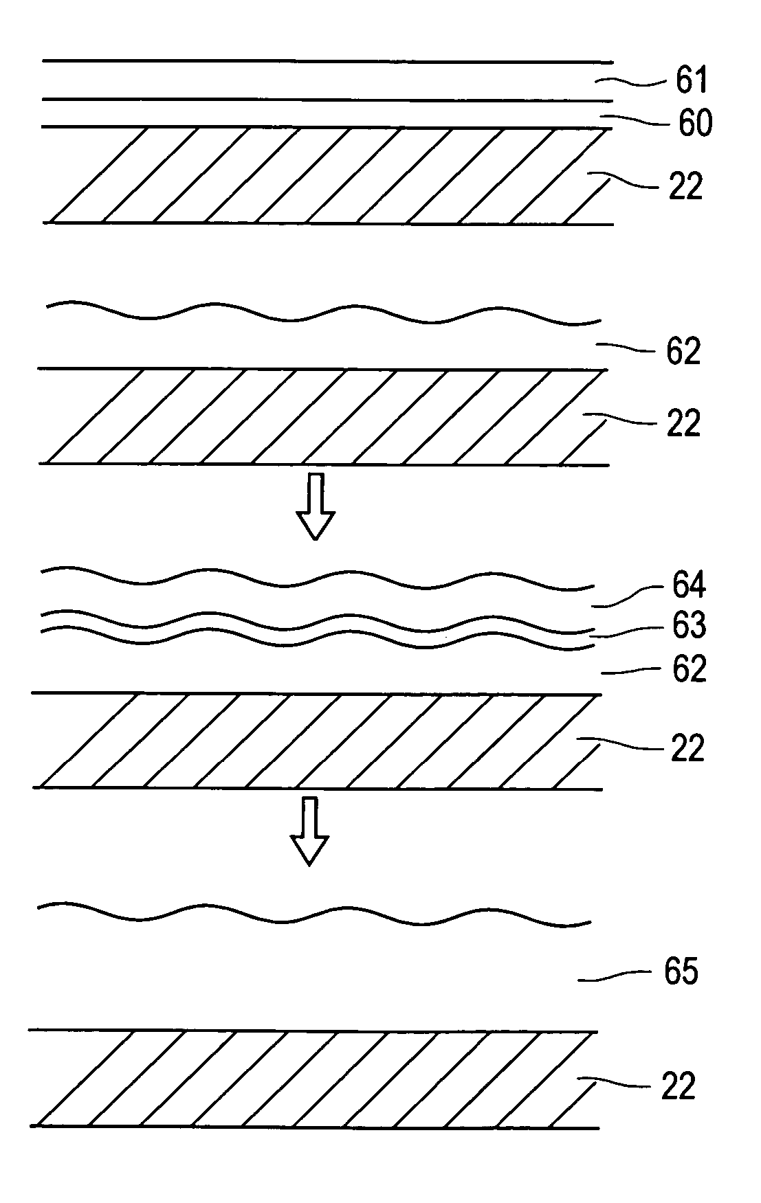
[0050]A Mo coated glass sheet may be used as the base. A 100 nm thick Cu layer may be deposited over the Mo layer. This is then followed by the deposition of a 220 nm thick In film and a 40 nm thick Ga layer. The stack is annealed at a temperature of 80-200° C. for 5-600 seconds to enhance alloying between Cu, In and Ga. Over the alloyed layer, 100 nm of Cu, 220 nm of In and 40 nm of Ga are then deposited or applied. The precursor is selenized by well known approaches such as in hydrogen selenide gas or selenium vapor to form the Cu0.8In0.8Ga0.2Se1.9 compound. It should be noted that selenization may be carried out by various other means such as depositing Se over the metallic precursor and heating up the stacked layer, heating the substrate in a Se-containing gaseous or liquid atmosphere etc. for times ranging from 5 minutes to 60 minutes.

example 2

[0051]A Mo coated glass sheet may be used as the base. A 100 nm thick Cu layer may be deposited over the Mo layer. This is then followed by the deposition of a 220 nm thick In film and a 40 nm thick Ga layer. The stack is annealed at a temperature of 80-200° C. for 5-600 seconds to enhance alloying between Cu, In and Ga. Over the alloyed layer, a 100 nm of Cu, a 220 nm of In and 40 nm of Ga are then deposited. A second anneal step is applied at 80-200° C. for 5-600 seconds to promote further alloying between the layers of the metallic precursor. The precursor thus obtained is then selenized by well known approaches such as in hydrogen selenide or selenium vapor to form the Cu0.8In0.8Ga0.2Se1.9 compound. It should be noted that selenization may be carried out by various other means such as depositing Se over the metallic precursor and heating up the stacked layer, heating the substrate in a Se-containing gaseous or liquid atmosphere etc. for times ranging from 5 minutes to 60 minutes...

example 3

[0052]The approaches in Example 1 or Example 2 are used except that Cu, In and Ga layers may be deposited in four steps instead of two steps. Accordingly, thickness of Cu, In and Ga for each deposition step may be reduced to 50 nm, 110 nm and 20 nm, respectively. By heat treating the layers after each deposition step for reduced times of preferably 2-300 seconds (except for the last one for the case of Example 1), a smooth and compositionally uniform metallic precursor may be obtained. Selenization of this precursor yields compositionally uniform, high quality Cu0.8In0.8Ga0.2Se1.9 compound layer.

[0053]In another embodiment of the present invention the morphology of the deposited films are further improved and the micro-scale compositional uniformity is further enhanced by dividing the metallic precursor preparation step into at least two sub-steps and selecting the composition of the sub-layers deposited by the sub-steps such that the sub-layers deposited early on the base do not co...


PUM

PropertyMeasurementUnit
temperatureaaaaaaaaaa
molar ratioaaaaaaaaaa

Abstract

The present invention advantageously provides for, in different embodiments, low-cost deposition techniques to form high-quality, dense, well-adhering Group IBIIIAVIA compound thin films with macro-scale as well as micro-scale compositional uniformities. In one embodiment, there is provided a method of growing a Group IBIIIAVIA semiconductor layer on a base, and includes the steps of depositing on the base a film of Group IB material and at least one layer of Group IIIA material, intermixing the film of Group IB material and the at least one layer of Group IIIA material to form an intermixed layer, and forming over the intermixed layer a metallic film comprising at least one of a Group IIIA material sub-layer and a Group IB material sub-layer. Other embodiments are also described.

Description

CROSS-REFERENCE TO RELATED APPLICATION[0001]This application claims the benefit of prior U.S. Provisional Application Ser. No. 60 / 552,736, filed Mar. 15, 2004 and incorporated herein by reference.FIELD OF THE INVENTION[0002]The present invention relates to method and apparatus for preparing thin films of semiconductors for radiation detector and photovoltaic applications.BACKGROUND[0003]Solar cells are photovoltaic devices that convert sunlight directly into electrical power. The most common solar cell material is silicon, which is in the form of single or polycrystalline wafers. However, the cost of electricity generated using silicon-based solar cells is higher than the cost of electricity generated by the more traditional methods. Therefore, since early 1970's there has been an effort to reduce cost of solar cells for terrestrial use. One way of reducing the cost of solar cells is to develop low-cost thin film growth techniques that can deposit solar-cell-quality absorber materia...

Claims


Application Information

Patent Timeline
Patent Type & Authority Patents(United States)
IPC IPC(8): H01L21/00H01L21/06
CPCH01L21/02568H01L21/02614H01L21/02628H01L31/0322Y02E10/541H01L31/0445H01L31/18H01L31/0749
Inventor BASOL, BULENT M.
Owner SOLOPOWER
Why Eureka
Try Eureka