Method of depressurizing cross radiation using an acoustically resistive leak path

a cross-radiation, acoustically resistive technology, applied in the field of loudspeakers, can solve the problems of contaminating directivity behavior, negatively altering the summation, and creating interference distortion, so as to reduce the mf energy and minimize the energy of the return path

Active Publication Date: 2021-11-23
BIAMP SYST LLC
View PDF7 Cites 0 Cited by
  • Summary
  • Abstract
  • Description
  • Claims
  • Application Information

AI Technical Summary

Benefits of technology

[0015]The present invention is a method of reducing MF energy through the use of small depressurizing slit openings down the inner half of the HF stems. The openings are sized to be large enough to present a leak path for the secondary energy to migrate out of the stem greatly minimizing any return path energy.

Problems solved by technology

In this case, the timing relationship between transducers becomes a function of angle from the loudspeaker central “axis.” Timing inconsistencies directly relate to summation distortion, thus contaminating directivity behavior.
1) The different transducers take up their own individual space and must therefore energize the horn and manifold structure from different local positions. This can lead to timing (i.e., phase) issues between each individual wave front which can negatively alter the summation.
2) The source openings into the horn or manifold from the different transducers create perturbations and acoustic “side” chambers for the neighboring elements. This creates secondary energy paths that include chamber resonances and trailing energy which, over time, creates interference distortion.
3) Transducers that must be positioned in horn or manifold mid-path entry points will naturally create a forward and rearward progressive wave leading to multiple paths for the same source. Similar to the secondary path energy stated in #2 above, the secondary energy results in interference distortion.
4) Certain design geometries create standing wave behavior within the manifold and / or horn body that also leads to distortion in the form of interference behavior and resonant tones.

Method used


Image

  • Method of depressurizing cross radiation using an acoustically resistive leak path
  • Method of depressurizing cross radiation using an acoustically resistive leak path
  • Method of depressurizing cross radiation using an acoustically resistive leak path

Examples


Embodiment Construction

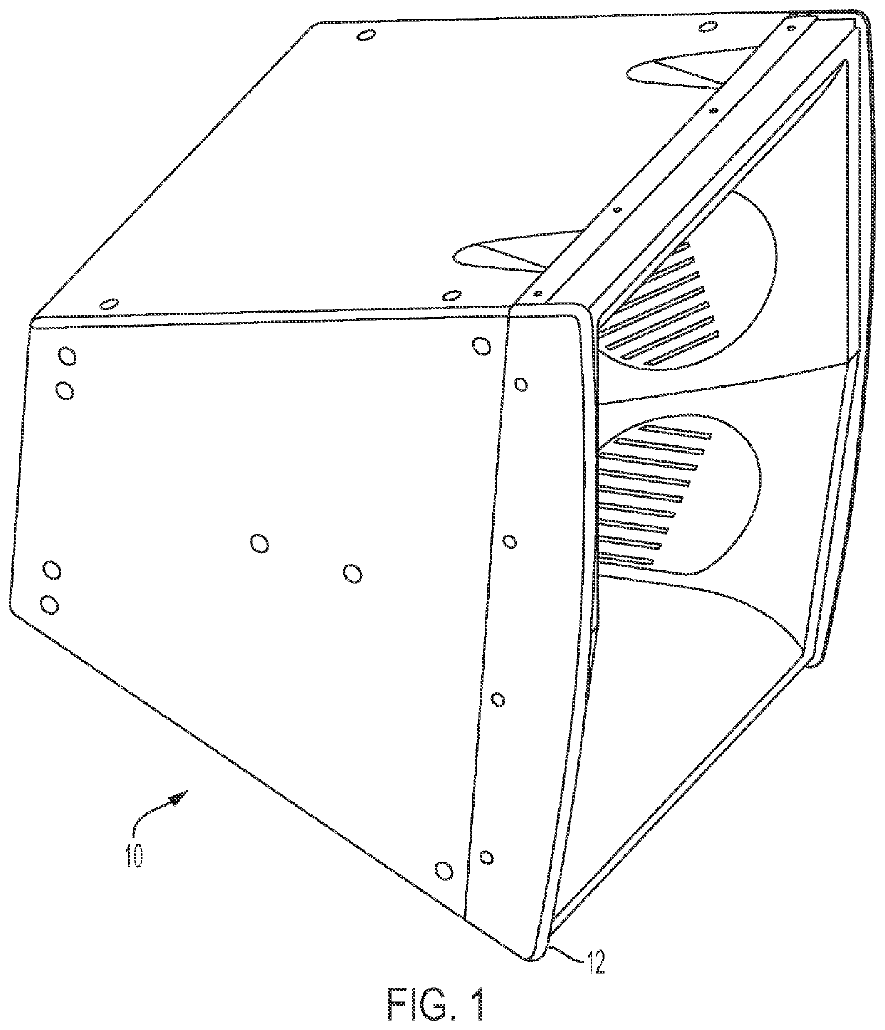
[0028]The present invention will be described in connection with a three-way horn loudspeaker 10 as illustrated in FIG. 1. The present invention may be used in connection with other combinations but, as will be recognized by one skilled in the art, the horn 10 preferably includes a MF and HF transducers.

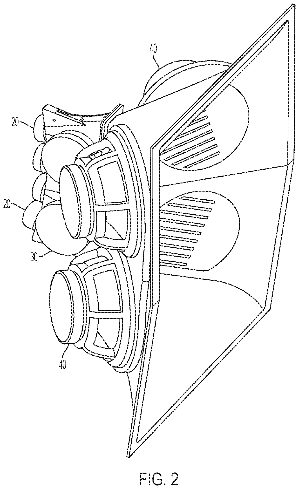
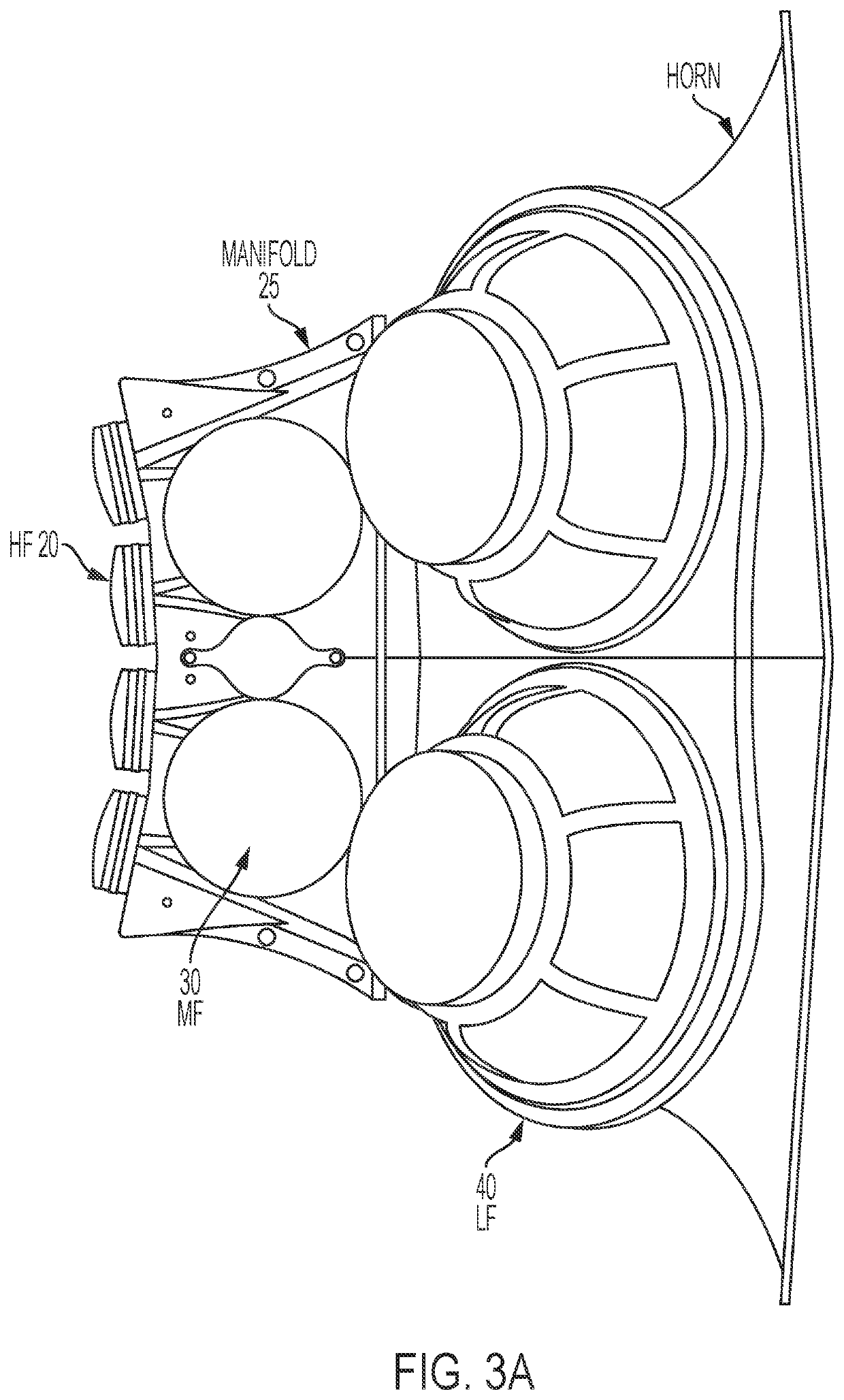
[0029]Referring now to FIG. 2, the horn loudspeaker 10 of FIG. 1 is illustrated without the outer enclosure 12. For the purposes of this disclosure, the horn 10 is a three-way loudspeaker including high frequency (HF) transducers 20, mid-frequency (MF) transducers 30, and low frequency (LF) transducers 40. As mentioned previously, the choice of multiple sized transducers is well known in the art and relates to optimizing radiation efficiency and performance criteria such as linearity, transient behavior, low distortion, etc.

[0030]The present invention is constrained by the design obstacles delineated previously. In producing a loudspeaker to overcome these design obstacles, several k...


PUM


Abstract

A method that improves the energy distribution from a multi-way loudspeaker into free space. The method reduces MF energy through the use of small depressurizing slit openings down the inner half of the HF stems. The openings are sized to be large enough to present a leak path for the secondary energy to migrate out of the stem with no return path.

Description

TECHNICAL FIELD[0001]The present invention relates generally to loudspeakers and, more specifically, to a means for improving the energy distribution of the sound waves from loudspeakers into free space.BACKGROUND[0002]Multiple-frequency (usually referred to as “multi-way”) loudspeakers are well-known in the art. The term “multi-way” indicates that the loudspeaker has more than one transducer—each transducer covering different audio frequency ranges. (The term “transducer” is generally synonymous with the terms “speaker,” or “driver.”) Even non-experts are familiar with two-way and three-way speakers which can be found in loudspeakers designed for the home or automobile.[0003]A typical three-way loudspeaker indicates that the loudspeaker includes a high-frequency transducer, a mid-range transducer, and a low-frequency transducer.[0004]The Background Section of U.S. Pat. No. 8,607,922 provides some information on the state of the art of multi-way loudspeakers. U.S. Pat. No. 8,607,922...

Claims


Application Information

Patent Timeline
Patent Type & Authority Patents(United States)
IPC IPC(8): H04R1/30H04R1/02H04R1/24
CPCH04R1/30H04R1/025H04R1/24
Inventor PEACE, JR., PAUL W.
Owner BIAMP SYST LLC
Why Eureka
Try Eureka