Distance measuring device
a technology of distance measurement and measuring device, which is applied in the direction of measurement device, using reradiation, instruments, etc., can solve the problems of lengthening the time required for the pair of light emission and exposure, and requiring longer measurement time. to achieve the effect of efficient measurement of distan
- Summary
- Abstract
- Description
- Claims
- Application Information
AI Technical Summary
Benefits of technology
Problems solved by technology
Method used
Image
Examples
embodiment 1
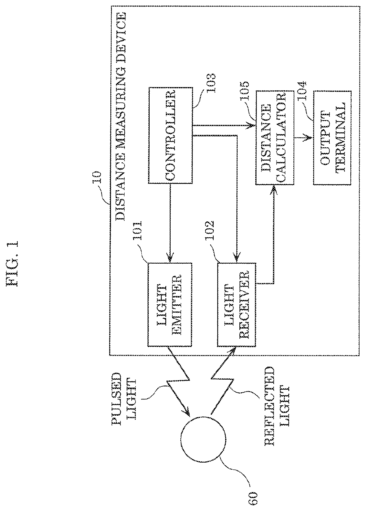
[0044]FIG. 1 is a block diagram indicating an example of a functional configuration of distance measuring device 10 according to this embodiment.
[0045]Distance measuring device 10 illustrated in FIG. 1 includes: light emitter 101; light receiver 102; controller 103; output terminal 104; and distance calculator 105. FIG. 1 illustrates measurement target 60 as an example.
[0046]Light emitter 101 is controlled by controller 103, and emits emission light. Light emitter 101 includes a light source such as a laser light source, and outputs a light pulse (emission light) by causing the light source to emit light having a predetermined light pulse width. It is to be noted that the intensity of a light pulse that is emitted by light emitter 101 is, for example, approximately at class 1 or class 2 which are not regarded as involving danger according to a predetermined safety standard.
[0047]A light source that emits light having a single wavelength, a short pulse, and strong intensity is suitab...
embodiment 2
[0102]Although a case where there is no limitation on measurement condition determining methods performed in the first time period and the second time period is described in Embodiment 1, measurement conditions in a second time period may be determined according to the result of measuring distance data in a first time period as indicated below. Specifically, controller 103 may determine the measurement conditions in the second time period based on the distance from distance measuring device 10 to measurement target 60 calculated in the first time period. This case is described below as Embodiment 2 focusing on differences from Embodiment 1.
[0103]Distance measuring device 10 according to this embodiment is different from distance measuring device 10 according to Embodiment 1 in operation details of controller 103 and distance calculator 105.
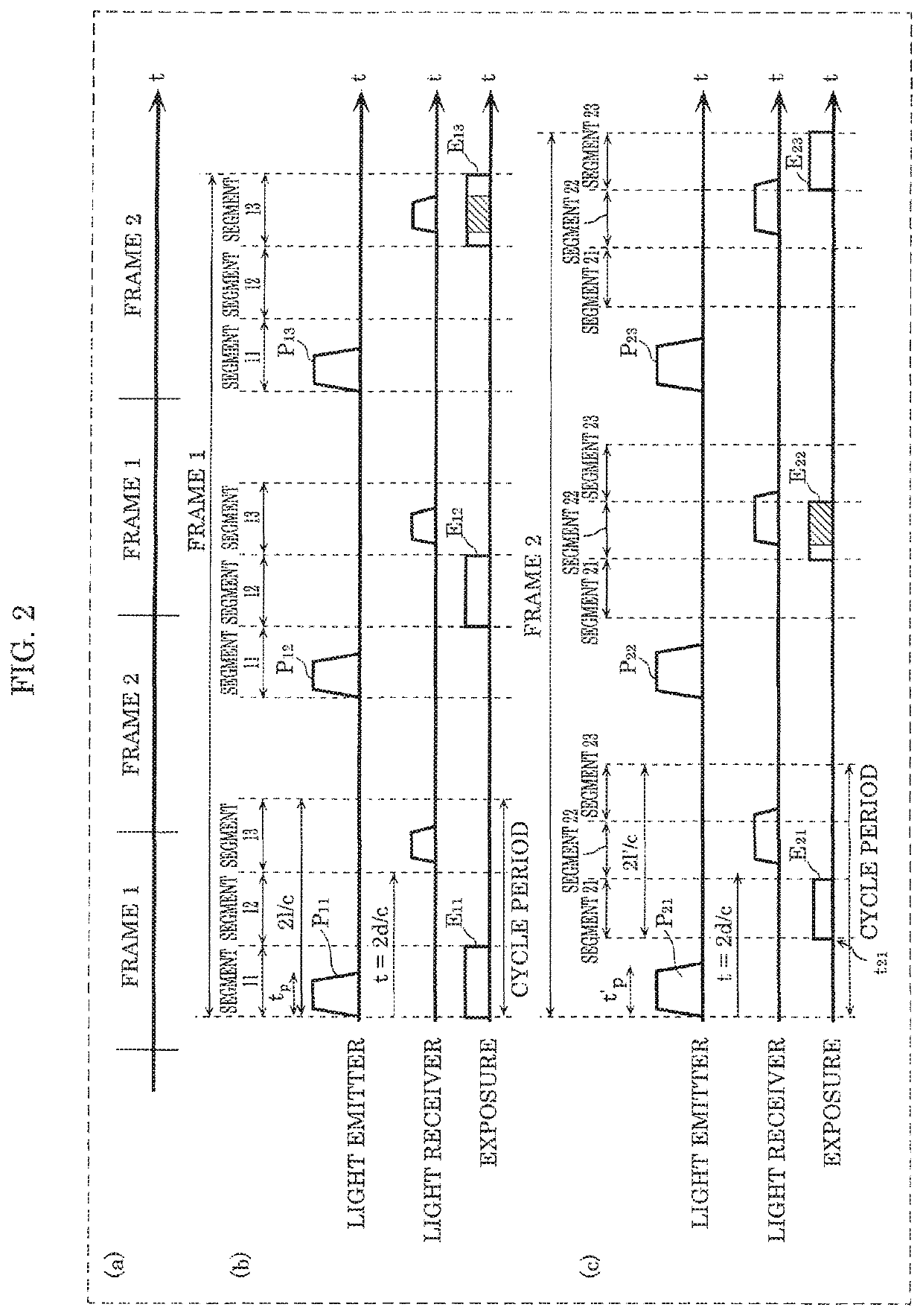
[0104]Specifically, controller 103 divides a first measurement time range into K (K is a natural number greater than or equal to 1) segment(s) in...
embodiment 3
[0134]A case where distance measuring device 10 and measurement target 60 have motions, for example, by moving is not mentioned in Embodiments 1 and 2. In this embodiment, a case where one of distance measuring device 10 and measurement target 60 is moving is described focusing on differences from Embodiments 1 and 2.
[0135]Distance measuring device 10 according to this embodiment is different from distance measuring device 10 according to Embodiments 1 and 2 in operation details of controller 103 and distance calculator 105.
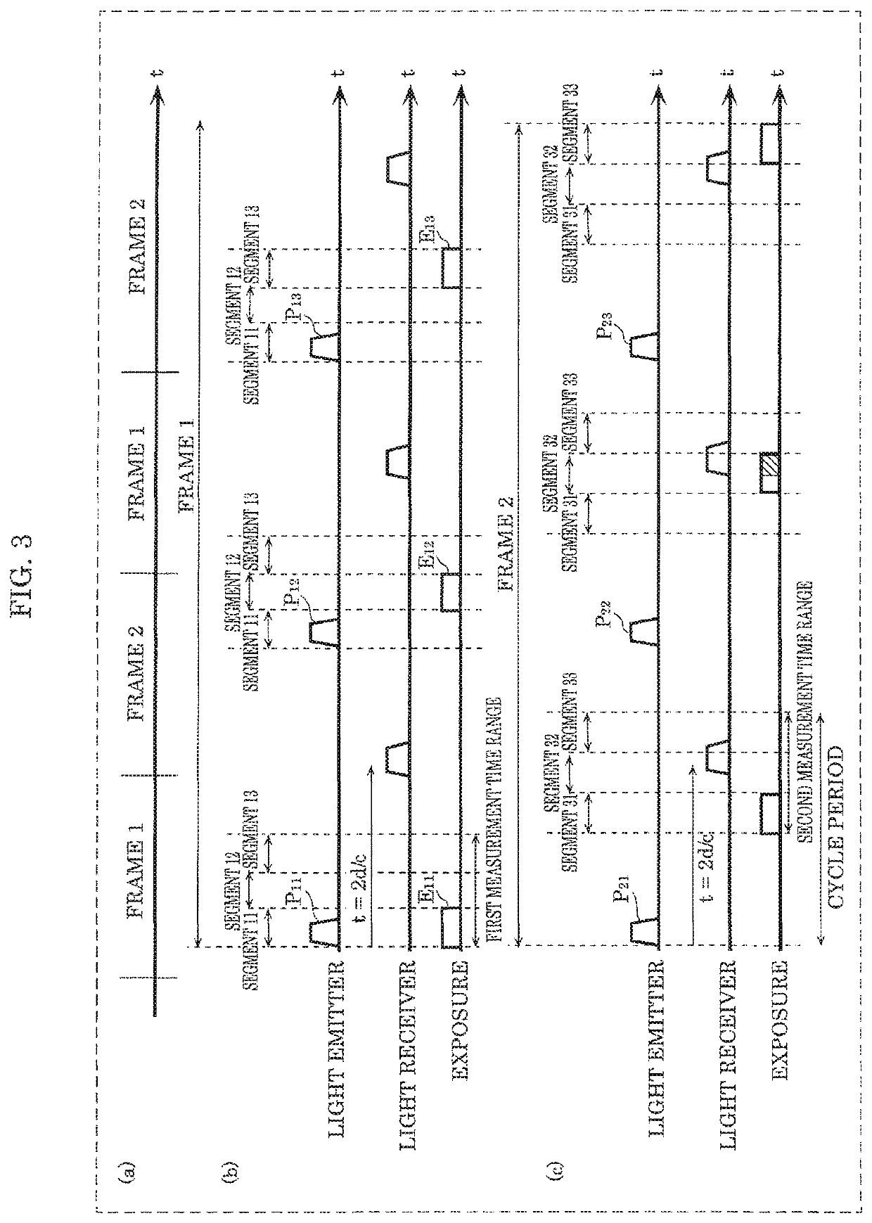
[0136]It is assumed that controller 103 confirms that measurement target 60 from which light receiver 102 received reflected light is present in the N-th segment (N is a natural number larger than or equal to K′(M)) among K′(M) segments. In this case, controller 103 performs control of: dividing, into O segments (O is a natural number larger than or equal to 2), a third measurement time range which includes the N-th segment and is smaller than a second measuremen...
PUM
 Abstract
Description
Claims
Application Information
 - R&D
- Intellectual Property
- Life Sciences
- Materials
- Tech Scout
- Unparalleled Data Quality
- Higher Quality Content
- 60% Fewer Hallucinations
Browse by: Latest US Patents, China's latest patents, Technical Efficacy Thesaurus, Application Domain, Technology Topic, Popular Technical Reports.
© 2025 PatSnap. All rights reserved.Legal|Privacy policy|Modern Slavery Act Transparency Statement|Sitemap|About US| Contact US: help@patsnap.com


