Mobile body detection device, mobile body detection method, and mobile body detection program
program technology, applied in the field of mobile body detection devices, mobile body detection methods, and mobile body detection programs, can solve the problems of increasing the number of incidents and accidents such as falling to national treasure buildings or locations where people come, and the increase of intentional crashes for terrorism or mischief, so as to improve the accuracy of mobile body detection and prevent a mobile body detection failure
- Summary
- Abstract
- Description
- Claims
- Application Information
AI Technical Summary
Benefits of technology
Problems solved by technology
Method used
Image
Examples
exemplary embodiment 1
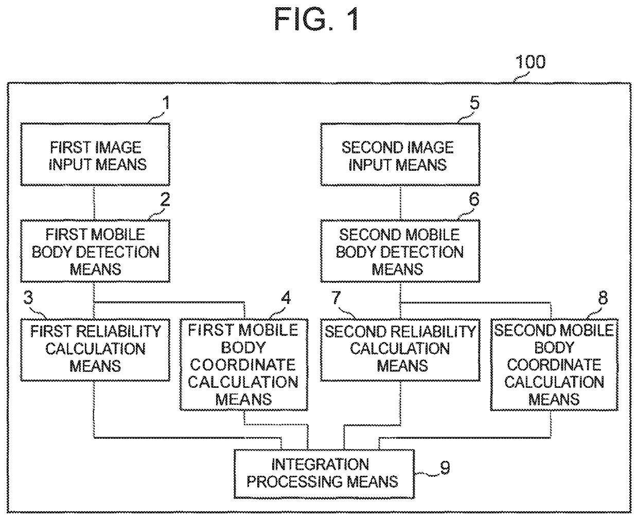
[0032]FIG. 1 is a block diagram depicting an example of a structure of Exemplary Embodiment 1 of a mobile body detection device according to the present invention. A mobile body detection device 100 in this exemplary embodiment includes a first image input means 1, a first mobile body detection means 2, a first reliability calculation means 3, a first mobile body coordinate calculation means 4, a second image input means 5, a second mobile body detection means 6, a second reliability calculation means 7, a second mobile body coordinate calculation means 8, and an integration processing means 9.
[0033]The mobile body detection device 100 in this exemplary embodiment (more specifically, the first image input means 1 and the second image input means 5) receives input of respective images captured by two types of imaging means that differ in sensitivity wavelength (detection wavelength). That is, two types of imaging means having different properties are used in this exemplary embodiment...
exemplary embodiment 2
[0071]Exemplary Embodiment 2 of a mobile body detection device according to the present invention will be described below. FIG. 5 is a block diagram depicting an example of a structure of Exemplary Embodiment 2 of a mobile body detection device according to the present invention. The same components as those in Exemplary Embodiment 1 are given the same reference signs as in FIG. 1, and their description is omitted.
[0072]A mobile body detection device 200 in this exemplary embodiment includes the first image input means 1, the first mobile body detection means 2, the first reliability calculation means 3, the first mobile body coordinate calculation means 4, a sensor information input means 10, a second mobile body detection means 11, a second reliability calculation means 12, a second mobile body coordinate calculation means 13, and the integration processing means 9.
[0073]That is, the mobile body detection device 200 in this exemplary embodiment differs from the mobile body detecti...
exemplary embodiment 3
[0099]Exemplary Embodiment 3 of a mobile body detection device according to the present invention will be described below. FIG. 8 is a block diagram depicting an example of a structure of Exemplary Embodiment 3 of a mobile body detection device according to the present invention. The same components as those in Exemplary Embodiment 2 are given the same reference signs as in FIG. 5, and their description is omitted.
[0100]A mobile body detection device 300 in this exemplary embodiment includes the first image input means 1, the first mobile body detection means 2, the first reliability calculation means 3, the first mobile body coordinate calculation means 4, the sensor information input means 10, the second mobile body detection means 11, the second reliability calculation means 12, the second mobile body coordinate calculation means 13, a reference signal generation means 14, and the integration processing means 9.
[0101]That is, the mobile body detection device 300 in this exemplary...
PUM
 Abstract
Description
Claims
Application Information
 - R&D
- Intellectual Property
- Life Sciences
- Materials
- Tech Scout
- Unparalleled Data Quality
- Higher Quality Content
- 60% Fewer Hallucinations
Browse by: Latest US Patents, China's latest patents, Technical Efficacy Thesaurus, Application Domain, Technology Topic, Popular Technical Reports.
© 2025 PatSnap. All rights reserved.Legal|Privacy policy|Modern Slavery Act Transparency Statement|Sitemap|About US| Contact US: help@patsnap.com


