Method for adjusting and visualizing parameters for focusing an objective lens on an object and system for implementing the method

a technology of objective lens and parameter setting, which is applied in the field of setting and visualizing parameters of the objective lens of the camera, can solve the problems of small depth of field accompanied by a disadvantage, the risk of moving objects moving out of the depth of field is ever present, and the recording of many times has to be repeated to achieve the effect of better estimation

Active Publication Date: 2021-12-28
CARL ZEISS SMT GMBH
View PDF14 Cites 0 Cited by
  • Summary
  • Abstract
  • Description
  • Claims
  • Application Information

AI Technical Summary

Benefits of technology

[0033]It is an object of the disclosure to provide a method for setting and visualizing parameters for focusing an objective lens and a system for performing the method, which are largely not susceptible to errors and which assist a focus puller in such a way that their artistic way of working is not impaired, and which allow the focus puller to move substantially freely over a film set and assume an optimized position in respect of their perspective and their image angle for setting the focusing.
[0048]Should the AR display and observation device be embodied as a pair of spectacles that communicates wirelessly with further units, a focus puller has the greatest freedom of movement on a film set where the camera is used. They are not fixed to a position and can move freely on the film set. Consequently, they can readily continue to perceive a scene of the film to be recorded using their eyes, to be precise at a freely chosen location and with a viewing angle depending on the chosen location, which gives them the best possible perspective for observing and anticipating the goings-on on the film set.
[0086]In a further embodiment of the method, provision is additionally or alternatively made for virtual markings to be displayed in the AR display and observation device, wherein the object will move along these virtual markings. This embodiment is advantageous, in particular, if the object to be imaged with the objective lens is in motion, for example a moving actor or a moving prop. The virtual markings help the focus puller better set the depth of field, which has to be repeatedly set anew on account of the movement, and better estimate the situation of the recording, that is, the imaging of the object. The virtual markings can take any form, for example they can be embodied as points or arrows. By way of example, the virtual markings may have been programmed before the imaging of the object and / or are calculated by a computer from movements, which are assembled from empirical values, for example, and / or on the basis of physical laws. However, the virtual markings could also represent objects that are subsequently worked into the recording by special effects. This also aids the focus puller with being able to better estimate the situation of the recording, that is, the imaging of the object.

Problems solved by technology

However, a small depth of field is accompanied by a disadvantage.
The risk of a moving object moving out of the depth of field is ever present when recording an image.
This is often undesirable.
However, even with many years of experience, recordings often have to be repeated due to the wrong focusing.
In film productions, this leads to delays and high costs, which is why a focus puller often is under very high emotional pressure.
Although this generally does not pose a particular risk to the actor, it is frequently not tolerated.
However, a disadvantage of this assistance system is that the functionality cannot be ensured on account of specific circumstances at the recording location, for example if steel girders or large metallic objects are present.
The steel girders or the large metallic objects impair the functionality.
Moreover, disturbance signals can be caused by external electromagnetic fields.
Consequently, there can also be incorrect settings of the focusing.
It was found that a further disadvantage of the known assistance systems is that they modify the way of working of the focus puller, namely the anticipation of the distance and probable movement of the object and / or the camera, and the readjustment of the focus by the focus puller.
Moreover, the focus can no longer be altered as desired, for example according to the specifications by a so-called director of photography (abbreviated DOP) or a cameraman.
This is often undesirable since the desired artistic effect of a recording is no longer achieved when the focus puller is replaced.

Method used


Image

  • Method for adjusting and visualizing parameters for focusing an objective lens on an object and system for implementing the method
  • Method for adjusting and visualizing parameters for focusing an objective lens on an object and system for implementing the method
  • Method for adjusting and visualizing parameters for focusing an objective lens on an object and system for implementing the method

Examples


Embodiment Construction

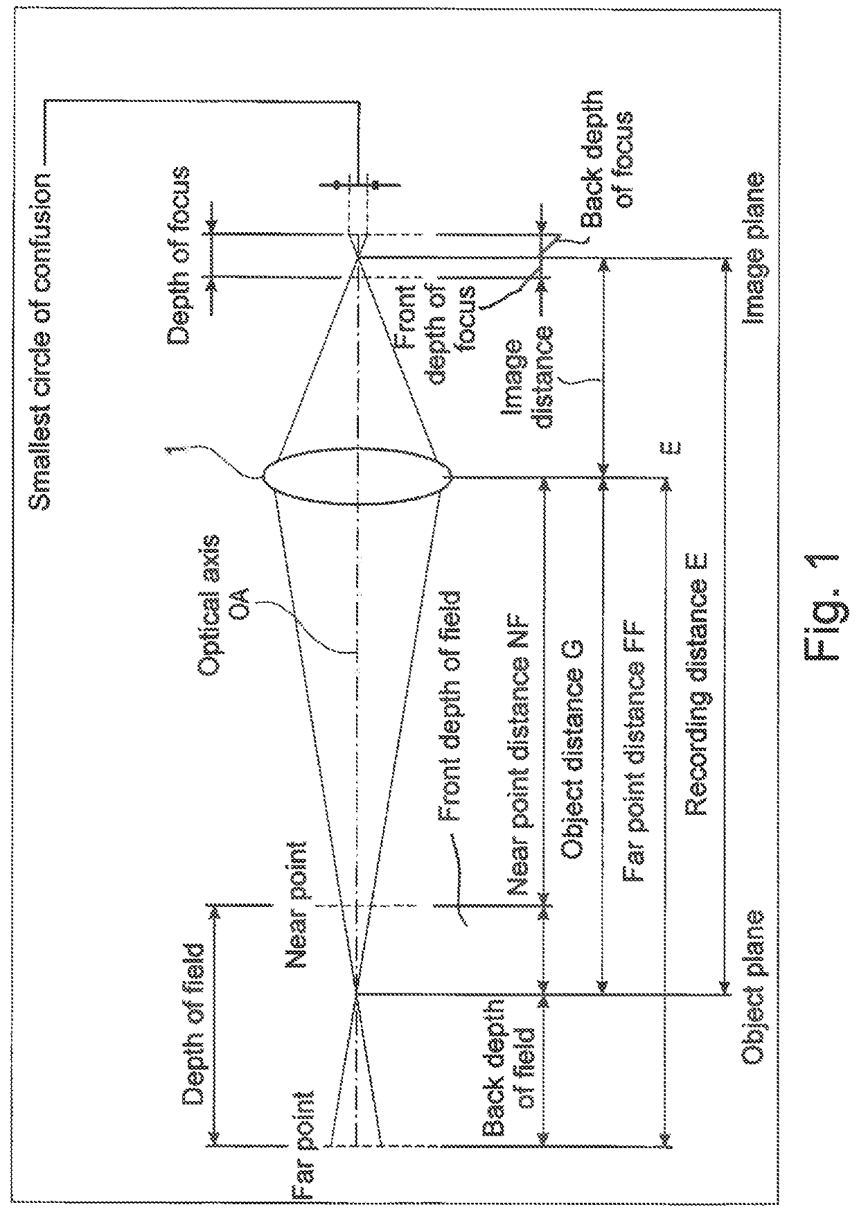
[0116]Initially, reference is made again to FIG. 1. FIG. 1 shows a schematic illustration of an objective lens 1 of a camera. By way of example, the objective lens 1 has one or more lens elements, which are not illustrated in FIG. 1. Moreover, the objective lens 1 has an aperture unit, which is not illustrated for reasons of clarity in the schematic illustration of FIG. 1. The aperture unit is provided with an adjustable aperture, which has a diameter. For the purposes of focusing the objective lens 1 on an object plane, the lens element or the plurality of lens elements are embodied to be movable along an optical axis OA of the objective lens 1. The object, situated in the object plane, to be imaged with the objective lens 1 is disposed at a recording distance E from the image plane. As already explained above, the relative position and alignment of the depth of field of the objective lens 1 is implemented by calculating a far point distance and a near point distance, wherein the f...


PUM


Abstract

The disclosure relates to a method for setting and visualizing parameters of an objective lens of a camera, in particular for focusing on a moving object, and to a system for per-forming the method. The camera is, for example, embodied as a film camera, in particular as a film camera used in cinematography. The method includes the following steps: calcu-lating a relative position and an alignment of a depth of field of the objective lens in the 3D space, observing the 3D space and / or the object with an AR display and observation de-vice, displaying the relative position and the alignment of the depth of field of the objective lens as an image in the AR display and observation device and / or displaying a focal plane as an image in the AR display and observation device, and setting the objective lens to ob-tain a desired depth of field of the objective lens.

Description

CROSS REFERENCE TO RELATED APPLICATION[0001]This application claims the priority of the German patent application No. 10 2019 111 238.9, filed on Apr. 30, 2019, which is hereby incorporated by reference.FIELD OF THE INVENTION[0002]The disclosure relates to a method for setting and visualizing parameters of an objective lens of a camera, in particular for focusing on a moving object. Further, the disclosure relates to system for performing the aforementioned method. By way of example, the camera is embodied as a film camera, in particular as a film camera used in the field of cinematography. In a further embodiment, the camera is embodied, for example, as a camera that is used in the field of photography.BACKGROUND OF THE INVENTION[0003]The practice of setting parameters of an objective lens manually or in motor-controlled fashion has already been known for a long time from the prior art. By way of example, the focal length and / or the aperture unit of an objective lens are set in man...

Claims


Application Information

Patent Timeline
Patent Type & Authority Patents(United States)
IPC IPC(8): G06T19/00G06T7/571G06F3/01
CPCG06T19/006G06T7/571G06F3/013G06F3/011H04N5/2228H04N23/67
Inventor HARTMANN, BENEDIKTWELKER, JOACHIMSTARK, CHRISTOPH
Owner CARL ZEISS SMT GMBH
Why Eureka
Try Eureka