Method for detecting insufficient contact pressure in a switching unit, device for implementing such a method, and switching unit including such a device

a switching unit and insufficient technology, applied in the direction of switch power arrangements, contact mechanisms, instruments, etc., can solve the problems of partial contact pressure in vacuum tubes, deterioration of the unit, and incomplete closure of the contacts of the uni

Active Publication Date: 2021-12-28
SCHNEIDER ELECTRIC IND SAS
View PDF4 Cites 44 Cited by
  • Summary
  • Abstract
  • Description
  • Claims
  • Application Information

AI Technical Summary

Benefits of technology

[0018]According to another feature, a range of duration of the current passing through the motor is defined and, for any current duration found within this range, it is deduced that there is normal operation without wear in the motor and in the specific parts of the mechanism for compressing the closure spring.

Problems solved by technology

These units can experience varied phenomena, such as very frequent use, corrosion, use at low temperature, etc.
These conditions can lead to the deterioration of the unit, particularly wear in the mechanism, the kinematic chain, the motor, or specifically in the parts for compressing the closure spring.
This wear in the mechanism, the kinematic chain or use at low temperature will result in incomplete closure of the contacts of the unit during a manoeuvre for closing the unit.
This incomplete closure leads to partial contact pressure in the vacuum tubes, and more broadly, in the switching components.
If the current is higher, the existence of this partial contact pressure before complete closure by the motor can lead to overheating and even destruction if the current level reaches the permissible short duration level or if there is a short circuit.
When the resetting is not carried out by a motor, the aforementioned problems resulting from incomplete closure occur even during closure on a nominal current.
These means nevertheless do not allow detection of the aforementioned wear and incomplete closure of the contacts.

Method used


Image

  • Method for detecting insufficient contact pressure in a switching unit, device for implementing such a method, and switching unit including such a device
  • Method for detecting insufficient contact pressure in a switching unit, device for implementing such a method, and switching unit including such a device
  • Method for detecting insufficient contact pressure in a switching unit, device for implementing such a method, and switching unit including such a device

Examples


Embodiment Construction

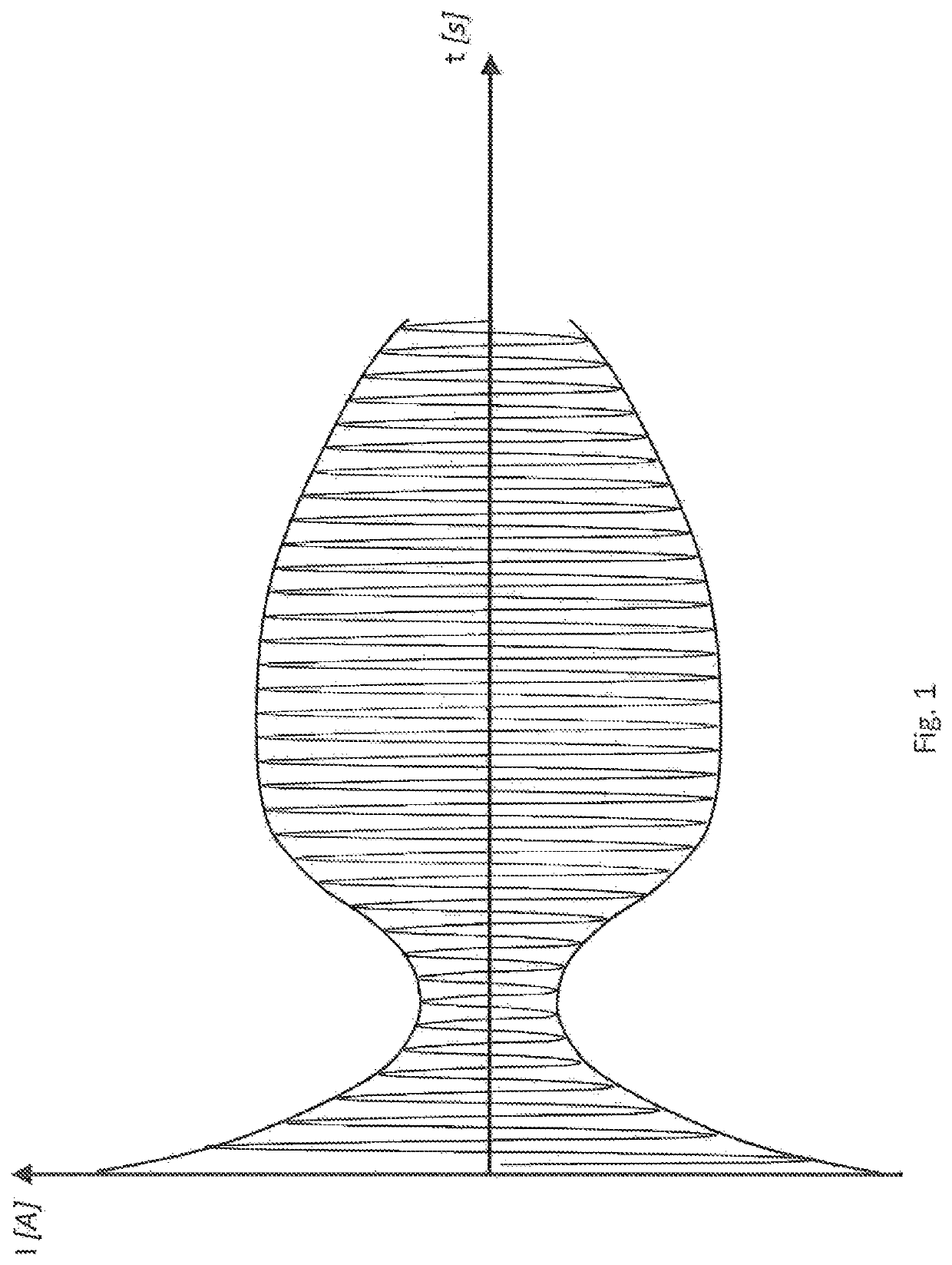
[0031]FIG. 1 shows an envelope curve representing the current consumed by a motor, said motor being intended to carry out the resetting of a mechanism for controlling the contacts of a switching unit, such as a medium voltage circuit breaker, on the basis of the duration of this resetting.

[0032]More specifically, these resetting means comprise means for storing the closure energy in the control mechanism so as to bring this control mechanism to a position in which it is ready to close the contacts of the unit. Advantageously, these resetting means comprise a closure spring.

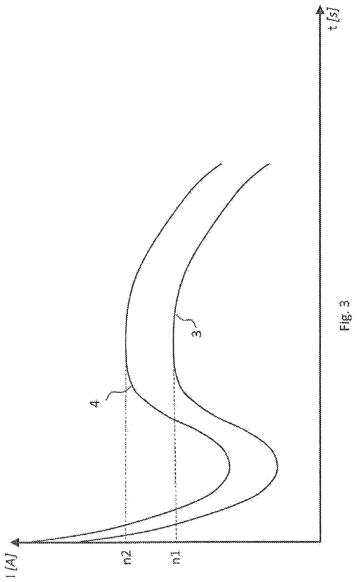
[0033]In FIG. 2, the first curve 1 corresponds to normal operation without any wear inside the switching unit, whereas the second curve 2 corresponds to incomplete closure of the contacts of the unit following wear in the mechanism, the kinematic chain, or even incomplete closure of the contacts of the unit exclusive of any wear, such as incomplete closure following use at low temperature.

[0034]As shown in this FI...


PUM


Abstract

A method for detecting insufficient contact pressure between two contacts of an electrical switching unit, including a device for resetting a mechanism for controlling the switching unit following a closure maneuver of the mechanism, the resetting device including a motor configured to complete the closure maneuver of the control mechanism. The method involves detecting whether the motor completes the closure and whether a resetting torque corresponds to a normal resetting torque, by analyzing an envelope curve of current consumed by the motor over time, and, if the motor completes the closure, deducing that a wear is a result of wear in the mechanism or a kinematic chain, and if the motor completes the closure and the resetting torque corresponds to an abnormal rescuing torque, deducing that the wear corresponds to wear in the motor or parts involved in compressing the closure spring.

Description

TECHNICAL FIELD[0001]The present invention relates to a method for detecting insufficient contact pressure between the two contacts of an electrical switching unit, said unit comprising means for resetting the mechanism for controlling the switching unit following closure of the mechanism, said means comprising means for compressing a closure spring intended to bring the mechanism for controlling the unit to a position in which it is ready to close, said resetting means also comprising a motor able to complete the closure manoeuvre of the control mechanism, in the event of incomplete closure by said control mechanism and before carrying out the resetting, said insufficient contact pressure being the result of wear in the mechanism, the kinematic chain, the motor, the parts involved in compressing the closure spring, or in the event of incomplete closure exclusive of any wear, for example, during periods of low temperatures that cause the greases to freeze.[0002]The present invention...

Claims


Application Information

Patent Timeline
Patent Type & Authority Patents(United States)
IPC IPC(8): H01H71/04H01H11/00H01H33/40H01H3/30
CPCH01H71/04H01H11/0062H01H33/40H01H2003/3094H01H2071/044H01H1/0015G01M13/023G01M13/02H01H1/50H01H3/26H01H3/30H01H33/36H01H71/70
Inventor GARAVELLI, JORDANEBECKER, STEEVE
Owner SCHNEIDER ELECTRIC IND SAS
Why Eureka
Try Eureka