
Pneumatic tire

a technology of pneumatic tires and tyres, applied in the field of pneumatic tires, can solve the problems of cavity resonance, vibration of tread sections, noise production, etc., and achieve the effect of facilitating the process of bonding the sound-absorbing member, and effective mitigation of shear strain

Active Publication Date: 2022-01-04
THE YOKOHAMA RUBBER CO LTD
View PDF10 Cites 0 Cited by
  • Summary
  • Abstract
  • Description
  • Claims
  • Application Information

AI Technical Summary

Benefits of technology

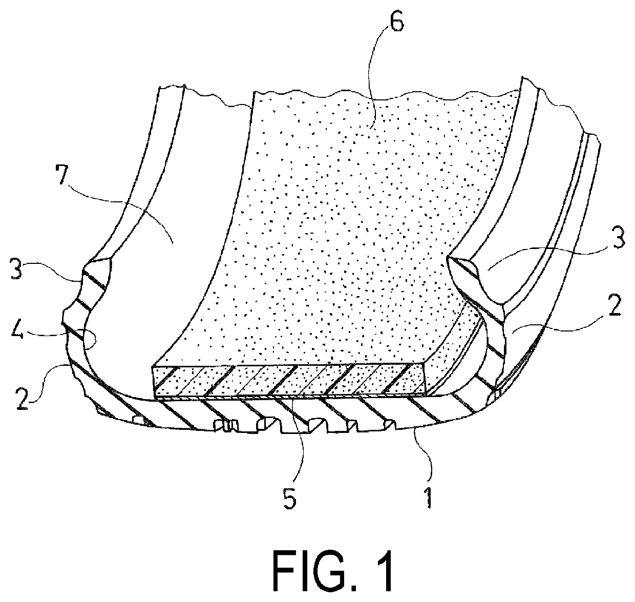
[0005]The present technology provides a pneumatic tire comprising a belt-shaped sound-absorbing member bonded to the inner surface of the tire in a region corresponding to a tread section, wherein it is possible to mitigate shear strain generated in the bonding surface of the sound-absorbing member and suppress peeling of the sound-absorbing member.

Problems solved by technology

In pneumatic tires, cavity resonance caused by the vibration of air filling the tire is one cause of noise production.
When a tire is rolled, uneven road surfaces cause a tread section to vibrate.
The vibrations of the tread section cause the air inside the tire to vibrate, which produces cavity resonance.
However, pneumatic tires exhibit radial growth caused by swelling during inflation or centrifugal force when traveling at high speeds, this radial growth generates shear strain in the bonding surface of the sound-absorbing member.
In addition, the tread section deforms when in contact with the ground; this deformation is also a factor leading to the generation of shear strain in the bonding surface of the sound-absorbing member.
When the bonding surface of sound-absorbing member bonded to the inner surface of the tire is subjected to repetitive shear strain over extended periods of time, the problem of peeling of the sound-absorbing member from the inner surface of the tire occurs.

Method used


Image

  • Pneumatic tire
  • Pneumatic tire
  • Pneumatic tire

Examples


examples

[0046]Tires according to a Comparative Example 1 and Working Examples 1 to 3 constituted by size 215 / 45R17 pneumatic tires provided with a ring-shaped tread section that extends in a circumferential direction of the tire, a pair of side wall sections disposed on both sides of the tread section, and a pair of bead sections disposed to the inside of the side wall sections with respect to a radial direction of the tire, a belt-shaped sound-absorbing member being bonded via an adhesive layer to an inner surface of the tire in a region corresponding to the tread section along the circumferential direction of the tire were prepared, with the sound-absorbing member being bonded in different manners in the various tires.

[0047]In Comparative Example 1, a cut-out section was provided at one location in the belt-shaped sound-absorbing member along the circumferential direction of the tire, and the entire bonding surface of the sound-absorbing member constituted a bonded region.

[0048]In Working...


PUM

PropertyMeasurementUnit
tolerance angleaaaaaaaaaa
tensile strengthaaaaaaaaaa

Abstract

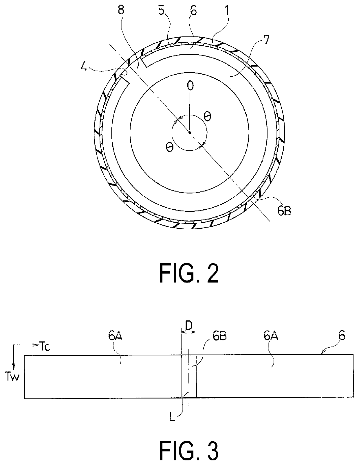
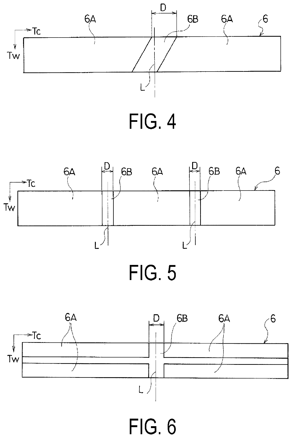
A pneumatic tire according to the present technology is a pneumatic tire provided with a tread section, sidewall sections, and bead sections, a belt-shaped sound-absorbing member being bonded via an adhesive layer to an inner surface of the tire in a region corresponding to the tread section along the circumferential direction of the tire, wherein a bonding surface of the sound-absorbing member is provided with a bonded region that is bonded to the inner surface of the tire and an unbonded region that is not bonded to the inner surface of the tire, and the bonded region is divided by the unbonded region into a plurality of divisions along the circumferential direction of the tire.

Description

TECHNICAL FIELD[0001]The present technology relates to a pneumatic tire comprising a belt-shaped sound-absorbing member bonded to an inner surface of the tire in a region corresponding to a tread section, and, more specifically, to a pneumatic tire that allows for the mitigation of shear strain occurring on a bonding surface of the sound-absorbing member and the suppression of peeling of the sound-absorbing member.BACKGROUND ART[0002]In pneumatic tires, cavity resonance caused by the vibration of air filling the tire is one cause of noise production. When a tire is rolled, uneven road surfaces cause a tread section to vibrate. The vibrations of the tread section cause the air inside the tire to vibrate, which produces cavity resonance.[0003]One proposed method for reducing the noise produced by this phenomenon of cavity resonance is to provide a sound-absorbing member within the cavity formed between the tire and the rim of the wheel. More specifically, a belt-shaped sound-absorbing...

Claims


Application Information

Patent Timeline
Patent Type & Authority Patents(United States)
IPC IPC(8): B60C19/00B60C1/00B60C11/00B60C13/00B60C15/00B29D30/00B32B3/08B60C5/00B32B3/28B32B5/18B32B7/12
CPCB60C19/002B29D30/0061B32B3/085B32B3/28B32B5/18B32B7/12B60C1/00B60C5/00B60C11/00B60C13/00B60C15/00B32B2307/102B32B2307/536B32B2307/54B32B2433/00B32B2605/08
Inventor TANNO, ATSUSHI
Owner THE YOKOHAMA RUBBER CO LTD
Learn More