

Supporting synergistic and retrofittable graph queries inside a relational database
a relational database and graph query technology, applied in relational databases, database models, instruments, etc., can solve the problems of iterative analysis and long running types
- Summary
- Abstract
- Description
- Claims
- Application Information
AI Technical Summary
Benefits of technology
Problems solved by technology
Method used
Image

Examples
example architecture
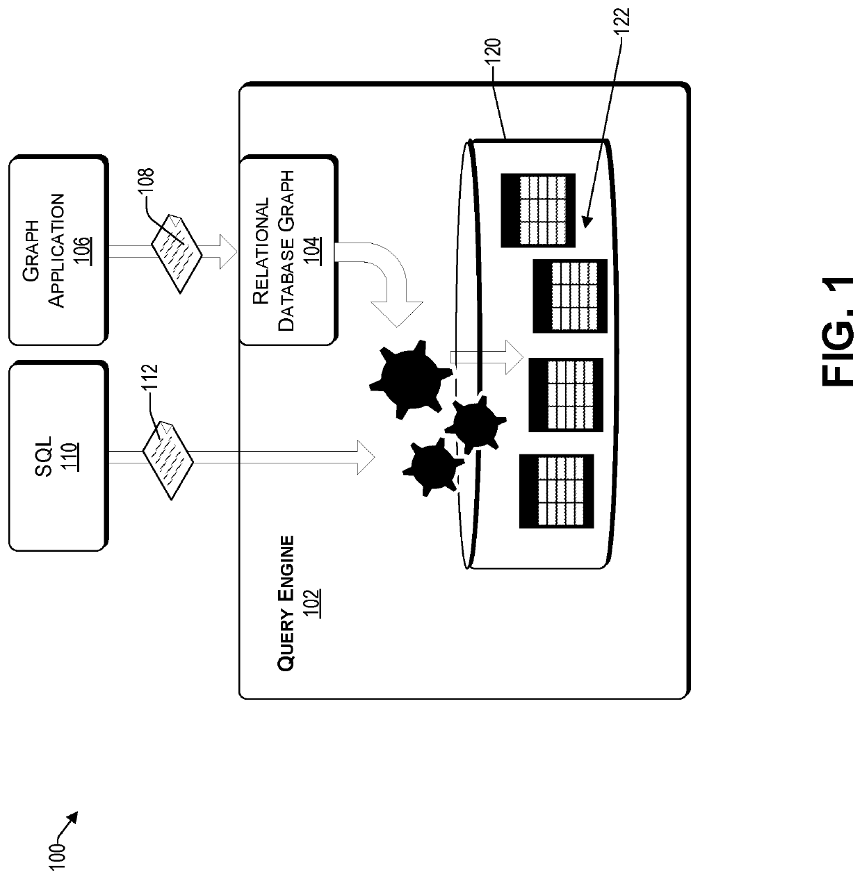
[0037]FIG. 1 illustrates an example architecture 100 of a relational database system that is able to process graph queries, consistent with an illustrative embodiment. The architecture 100 includes a relational database graph layer 104, which is a layer inside query engine 102 specialized for graph queries, as illustrated in FIG. 1. For example, the query engine is a relational database management system that is enhanced by a relational database graph 104 to be able to support graph queries 108 from graph applications 106. The relational database graph 104 is configured to receive a graph query 108 from a graph application 106 as the input and translate the request (i.e., query) into a set of SQL® queries 110. The translated query then executes the graph query 108 by utilizing the query engine 102 through SQL®110 by using a relational database 120, which may be a conventional relational database. Significantly, graph and SQL® queries 112 operate on the same data stored in the relati...
example implementation
[0068]Reference now is made to FIG. 9, which is an example architecture 900 of a relational database graph layer, consistent with an illustrative embodiment. It is a layer inside or before a relational database management system, sometimes referred to herein as a query engine. In one example, the relational database graph layer 910 is between a graph traversal language 906 (such as Gremlin®) providing queries 908, and a query engine 950. The relational database graph layer 910 includes a graph traversal module 920 operative to parse the input query 908 and generate query plans. In one embodiment, the graph traversal language is TinkerPop and the query plans are generated by way of Tinkerpop API calls. There are several modules 932 to 938 that are operative to support the graph traversal module 920. The modules include topology 932, graph structure 934, SQL® dialect 936, and traversal strategy 938. Together these modules implement the (e.g., Tinkerpop) core API with the help of the (...
example processes
[0091]With the foregoing overview of the example architectures 100 and 900, it may be helpful now to consider a high-level discussion of an example process. To that end, FIG. 10 presents an illustrative process related to performing a synergistic graph query on a relational database. Process 1000 is illustrated as a collection of blocks, each in a logical flowchart, which represent sequence of operations that can be implemented in hardware, software, or a combination thereof. In the context of software, the blocks represent computer-executable instructions that, when executed by one or more processors, perform the recited operations. Generally, computer-executable instructions may include routines, programs, objects, components, data structures, and the like that perform functions or implement abstract data types. In each process, the order in which the operations are described is not intended to be construed as a limitation, and any number of the described blocks can be combined in...
PUM
 Abstract
Description
Claims
Application Information