Light source device
a light source and light source technology, applied in the direction of solid-state devices, basic electric elements, lighting and heating apparatus, etc., can solve the problems of not being improved, and the conventional light source device is more and more difficult to meet various requirements. achieve the effect of improving the problems associated
- Summary
- Abstract
- Description
- Claims
- Application Information
AI Technical Summary
Benefits of technology
Problems solved by technology
Method used
Image
Examples
first embodiment
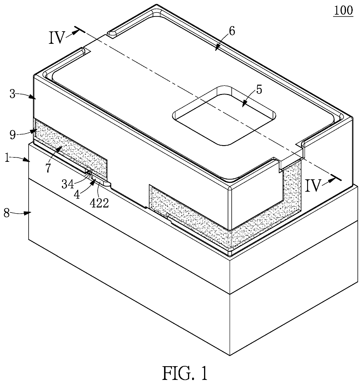
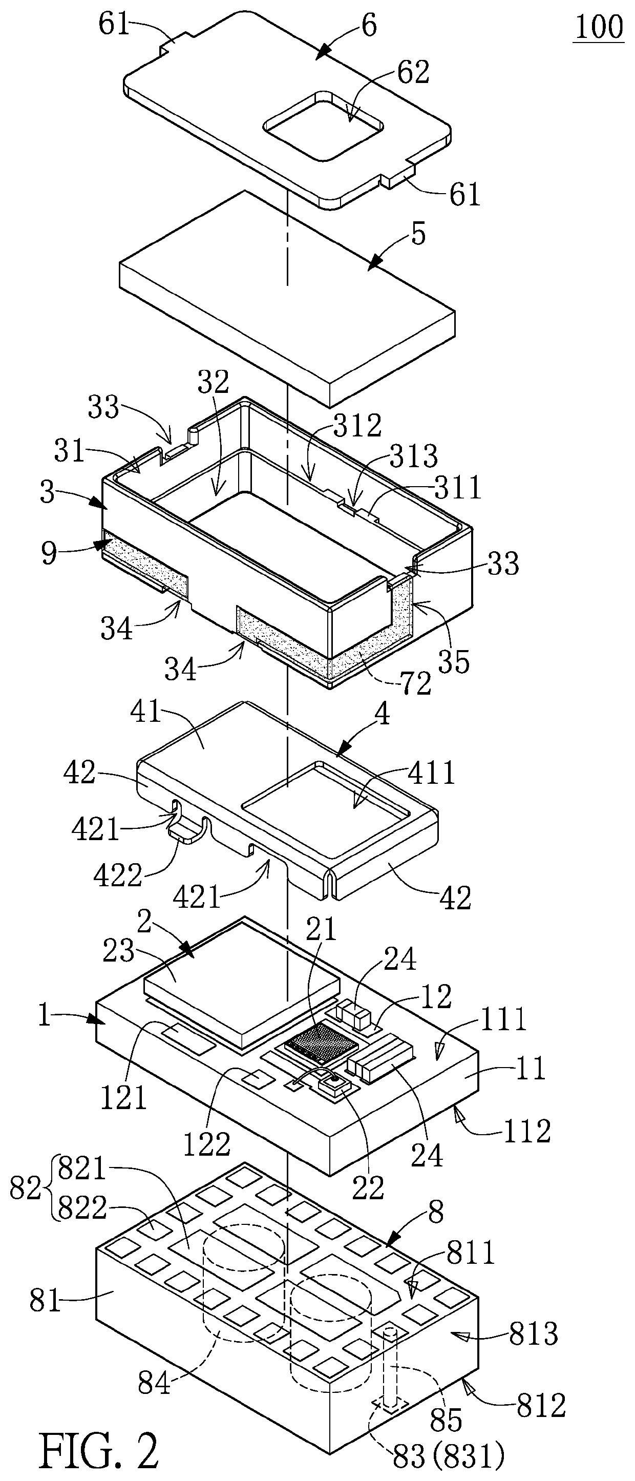
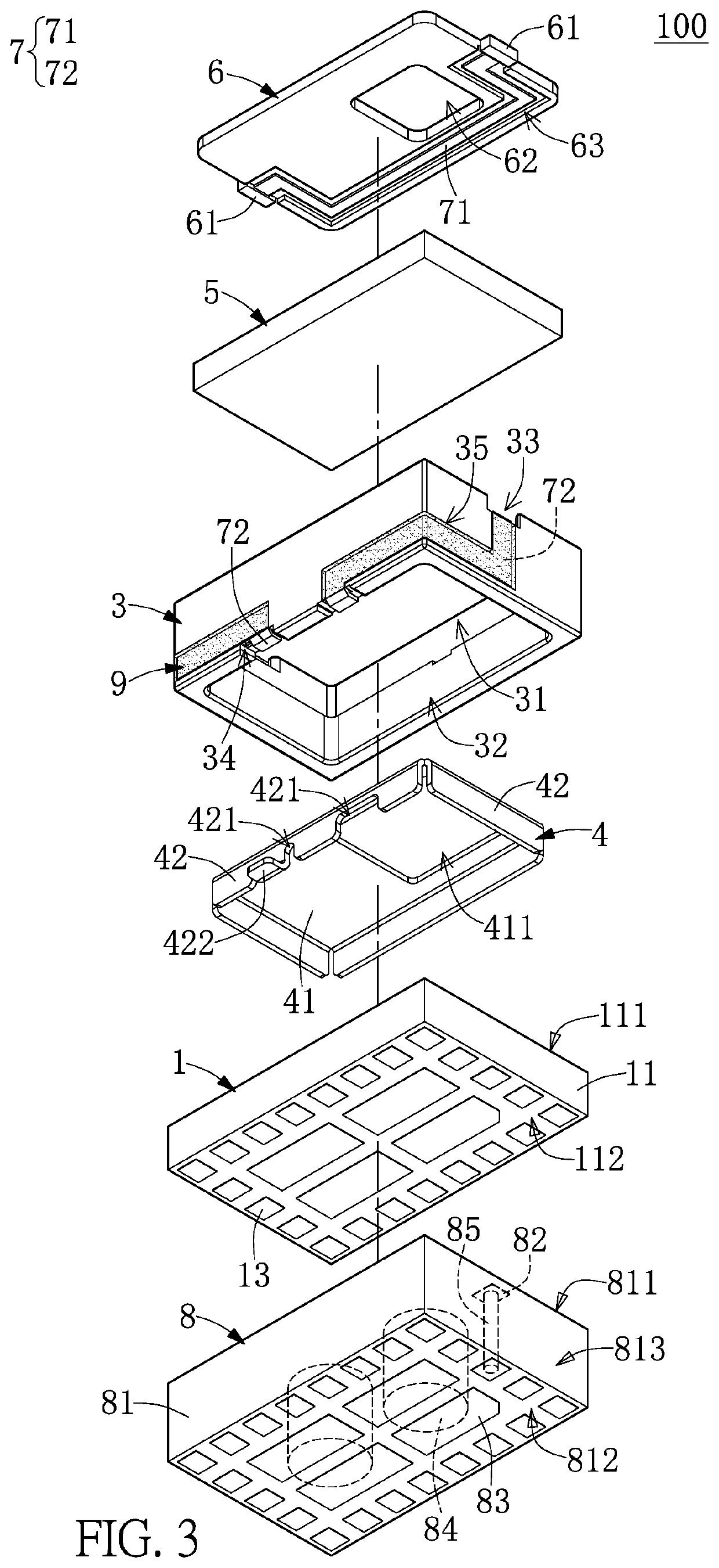
[0028]Referring to FIG. 1 to FIG. 4, a first embodiment of the present disclosure provides a light source device 100. The light source device 100 includes a substrate 1, a plurality of electronic components 2 mounted on the substrate 1, a frame 3 disposed on the substrate 1, a metal shield 4 fixed to an inner side of the frame 3 and electrically coupled to the substrate 1, a light permeable member 5 disposed on the frame 3, a cover plate 6 disposed on the light permeable member 5 and fixed to the frame 3, a detection unit 7 electrically coupled to the substrate 1, and an uplift block 8 that provides for the substrate 1 to be disposed thereon.
[0029]It should be noted that the light source device 100 in the present embodiment includes the above components, but the present disclosure is not limited thereto. For example, in other embodiments of the present disclosure, the light source device 100 can be provided without at least one of the above components (e.g., the metal shield 4, the ...
second embodiment
[0068]Referring to FIG. 9 to FIG. 11, a second embodiment of the present disclosure is similar to the first embodiment of the present disclosure. For the sake of brevity, descriptions of the same components in the first and second embodiments of the present disclosure (e.g., the substrate 1, the electronic components 2, the metal shield 4, and the uplift block 8) will be omitted, and the following description only discloses different features between the first and second embodiments.
[0069]In the present embodiment, the light source device 100 is provided without the cover plate 6 and the protection layers 9, and the frame 3 has an accommodating slot 31 recessed in the top side thereof. The accommodating slot 31 corresponds in position and shape to the opening 411 of the metal shield 4 (e.g., at least part of the driver chip 23 is covered by the metal shield 4 and the frame 3), and the frame 3 also has the glue-receiving channel and the air vent (not shown) recessed in the annular bo...
third embodiment
[0074]Referring to FIG. 12 and FIG. 13, a third embodiment of the present disclosure is similar to the second embodiment of the present disclosure. For the sake of brevity, descriptions of the same components in the third and second embodiments of the present disclosure will be omitted, and the following description only discloses different features between the third and third embodiments.
[0075]In the present embodiment, the frame 3 does not have the accommodating slot 31 that is used to receive the light permeable member 5. Specifically, the frame 3 has a light permeable opening 36 corresponding in position to the light emitting unit 21, the light permeable member 5 is arranged inside of the frame 3 and covers a bottom side of the light permeable opening 36. In other words, the light permeable member 5 is arranged in the accommodating space 32 of the frame 3, and the light permeable member 5 is adhered to an inner surface of an upper portion of the frame 3 in a reversely bonding ma...
PUM
| Property | Measurement | Unit |
|---|---|---|
| light permeable | aaaaa | aaaaa |
| area | aaaaa | aaaaa |
| height | aaaaa | aaaaa |
Abstract
Description
Claims
Application Information
 - R&D
- Intellectual Property
- Life Sciences
- Materials
- Tech Scout
- Unparalleled Data Quality
- Higher Quality Content
- 60% Fewer Hallucinations
Browse by: Latest US Patents, China's latest patents, Technical Efficacy Thesaurus, Application Domain, Technology Topic, Popular Technical Reports.
© 2025 PatSnap. All rights reserved.Legal|Privacy policy|Modern Slavery Act Transparency Statement|Sitemap|About US| Contact US: help@patsnap.com


