Mobile communication apparatus, optical assembly and aperture module of optical assembly
- Summary
- Abstract
- Description
- Claims
- Application Information
AI Technical Summary
Benefits of technology
Problems solved by technology
Method used
Image
Examples
first embodiment
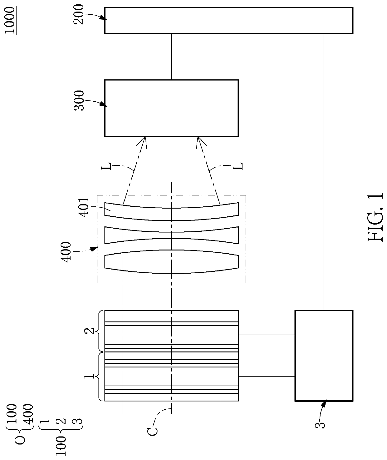
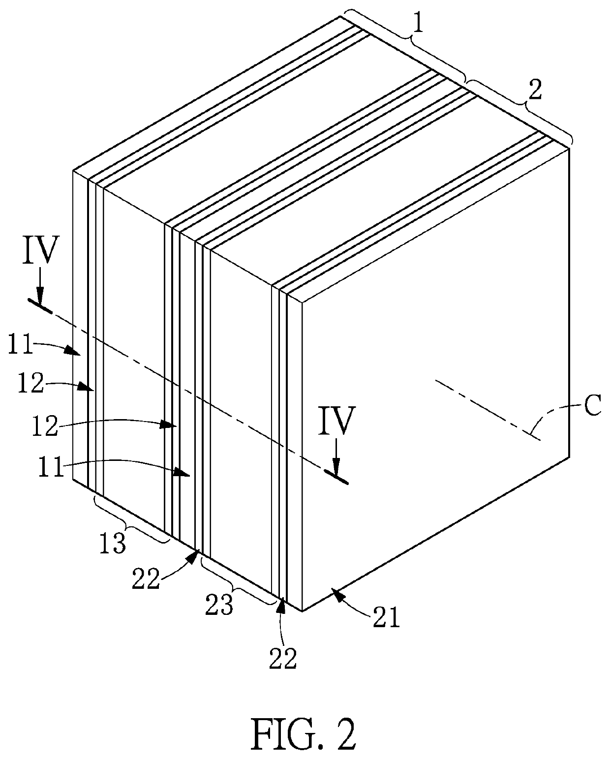
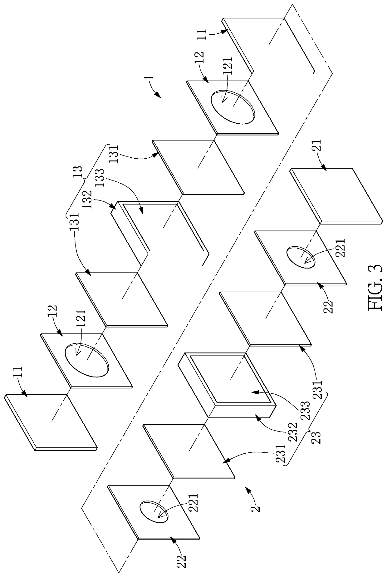
[0030]Referring to FIG. 1 to FIG. 5, a first embodiment of the present disclosure provides a mobile communication apparatus 1000 (e.g., a smart phone or a tablet PC). As shown in FIG. 1, the mobile communication apparatus 1000 includes a display 200, an image sensor 300 electrically coupled to the display 200, a lens module 400 corresponding in position to the image sensor 300, and an aperture module 100 that corresponds in position to the lens module 400 and is electrically coupled to the display 200. The lens module 400 and the aperture module 100 in the present embodiment can be jointly defined as an optical assembly O. However, in other embodiments of the present disclosure, the optical assembly O can be applied to other apparatus.
[0031]It should be noted that the display 200 in the present embodiment has a touch-control function, and the operation of the aperture module 100 can be controlled by the touch-control function of the display 200. The lens module 400 can be adjusted t...
second embodiment
[0061]Referring to FIG. 6 to FIG. 10, a second embodiment of the present disclosure is similar to the first embodiment of the present disclosure. For the sake of brevity, descriptions of the same components in the first and second embodiments of the present disclosure will be omitted, and the following description only discloses different features between the first and second embodiments.
[0062]In the present embodiment, as shown in FIG. 6 and FIG. 7, any one of the first LC aperture unit 1 and the second LC aperture unit 2 of the aperture module 100 can be independently used. Moreover, the first LC aperture unit 1 and the second LC aperture unit 2 are arranged at the optical axis C of the lens module 400 and are respectively disposed on two opposite sides of the lens module 400, but the present disclosure is not limited thereto.
[0063]Specifically, as shown in FIG. 9, since the structure of the first LC aperture unit 1 of the present embodiment is substantially identical to that of t...
third embodiment
[0066]Referring to FIG. 11 to FIG. 15, a third embodiment of the present disclosure is similar to the first and second embodiments of the present disclosure. For the sake of brevity, descriptions of the same components in the first to third embodiments of the present disclosure will be omitted, and the following description only discloses different features between the third embodiment and the first and second embodiments.
[0067]In the present embodiment, as shown in FIG. 11, FIG. 13, and FIG. 14, the first LC layer 13 includes two first orientation layers 131, an outer ring-shaped adhesive 132 connected to inner surfaces of the two first orientation layers 131, an inner ring-shaped adhesive 134 arranged inside of the outer ring-shaped adhesive 132 and connected to the inner surfaces of the two first orientation layers 131, and a first LC group 133. The inner ring-shaped adhesive 134 corresponds in position to the inner edge of each of the two first transparent electrode layers 12. I...
PUM
 Abstract
Description
Claims
Application Information
 - R&D
- Intellectual Property
- Life Sciences
- Materials
- Tech Scout
- Unparalleled Data Quality
- Higher Quality Content
- 60% Fewer Hallucinations
Browse by: Latest US Patents, China's latest patents, Technical Efficacy Thesaurus, Application Domain, Technology Topic, Popular Technical Reports.
© 2025 PatSnap. All rights reserved.Legal|Privacy policy|Modern Slavery Act Transparency Statement|Sitemap|About US| Contact US: help@patsnap.com


