Apparatus and method for generating a representation of a scene

a technology of scene and apparatus, applied in the field of apparatus and method for generating a scene, can solve the problems of difficult or impossible to meet requirements in many practical applications, difficult to achieve requirements for placement determination, and difficulty in achieving second points, so as to facilitate or enable interworking, improve quality, and enhance coverage

Active Publication Date: 2022-01-04
KONINKLJIJKE PHILIPS NV
View PDF5 Cites 0 Cited by
  • Summary
  • Abstract
  • Description
  • Claims
  • Application Information

AI Technical Summary

Benefits of technology

[0030]The invention may allow an improved and / or facilitated determination of placements of depth-sensing cameras capturing a scene thereby allowing an improved representation of the scene to be generated. In many embodiments and scenarios, a very accurate placement determination may be performed.
[0072]This may provide improved and / or facilitated operation and / or performance. The generator may be arranged to generate the image in response to an evaluation of the three-dimensional model

Problems solved by technology

However, as this may be considered inconvenient to the user, it is in many scenarios preferred to use autostereoscopic displays that use means at the display (such as lenticular lenses, or barriers) to separate views, and to send them in different directions where they individually may reach the user's eyes.
However, in many applications, the provided images may not directly correspond to the desired directions, or more images may be required.
However, a particular challenge when trying to develop and support flexible video and image applications supporting variable view positions and / or directions is that these are preferably not limited to a subset of positions and / or directions but all positions and / or directions are ideally supported.
This requirement is difficult or impossible to meet in many practical applications, such as specifically applications wherein the 3D data is based on captures of a real-world scene.
One of the most difficult challenges to address is that of how to effectively capture a scene such that a representation of the scene can be generated which provides sufficient information to allow suitable viewpoint images of sufficiently high quality to be generated yet still allowing the representation to be easily communicated, stored, adapted, and / or processed.
In particular the second point is often difficult and critical.
In many applications, the requirements for the placement determination are very demanding and difficult to achieve.
However, such an approach is impractical or even impossible in many applications.
For example, if a large number of cameras are used and / or if cameras are far from each other, it is typically not practical to manually measure or restrict positions and orientations to a high degree of accuracy.
Further, the approach is not suitable for dynamic capture applications, such as when cameras may be dynamically added or removed from the capture system, or where one or more of the cameras may be a moving camera.
However, this not only requires the depth camera sensors to include such functionality, which may often not be the case in practice, but further tends to provide results that are far from sufficiently precise to ensure accurate determination between different cameras, especially for orientation values.
However, the approach tends to be computationally very intensive as the image matching needs to in principle consider all regions of an image relative to all other regions in all other captured images.
Further, it has been found that the approach tends to give suboptimal and typically relatively inaccurate results.
For example, it is difficult to prevent accidental matching between image regions that do not represent the same object but rather different objects that may have similar visual properties (or the same object from very different directions).
Such mismatches may result in erroneous placement determination, which may result in significant errors when using this placement information to combine the data from different cameras.

Method used


Image

  • Apparatus and method for generating a representation of a scene
  • Apparatus and method for generating a representation of a scene
  • Apparatus and method for generating a representation of a scene

Examples


Embodiment Construction

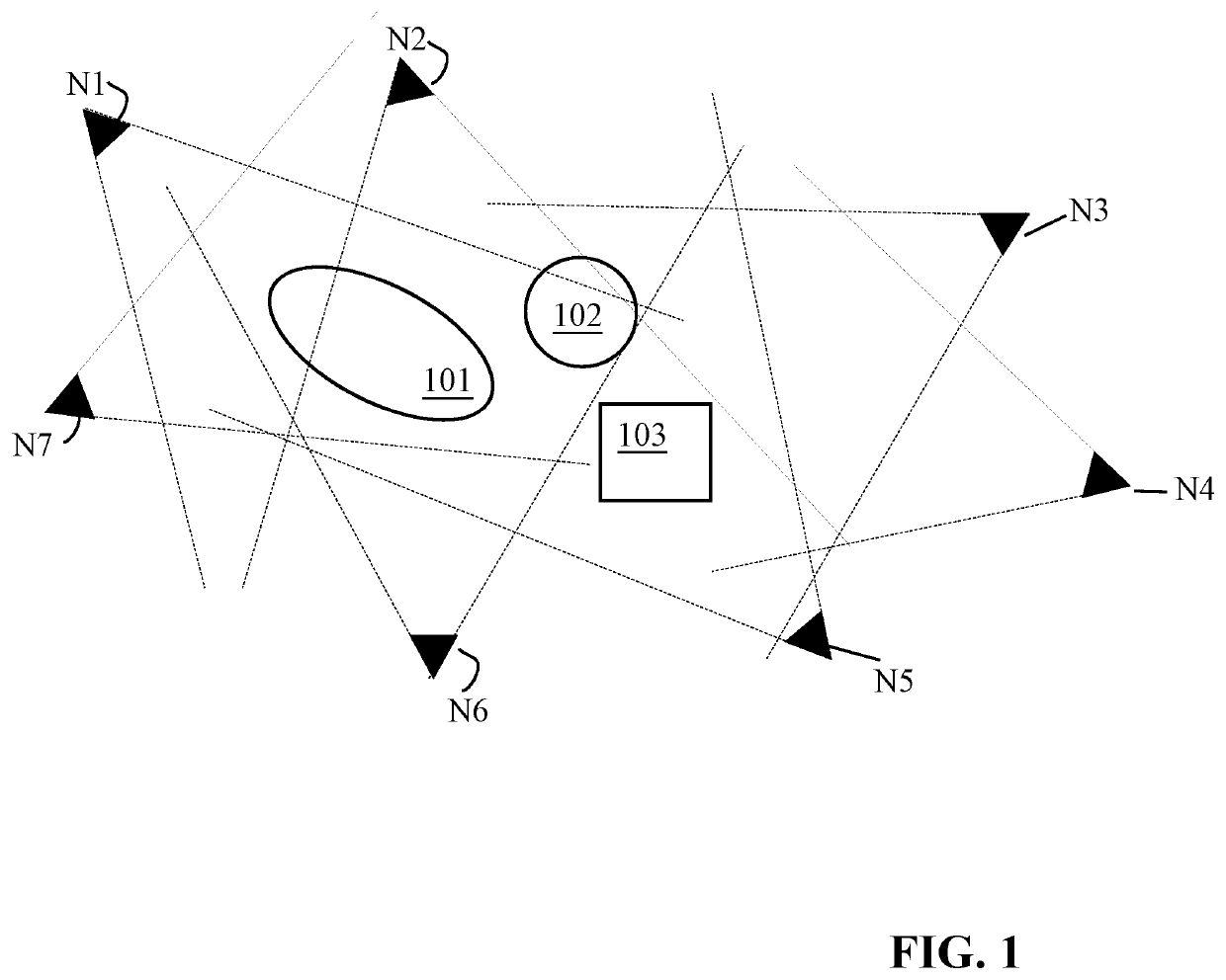
[0083]The following description focuses on embodiments of the invention applicable to generation of a data representation of a scene based on image (including video) captures from a plurality of distributed depth-sensing cameras, such as typically a capturing system comprising 10, 20 or even more cameras. However, it will be appreciated that the invention is applicable to many capturing systems including systems with only a few depth-sensing cameras capturing the scene.

[0084]FIG. 1 illustrates an example of a capturing system wherein a relatively large number of depth-sensing cameras capture a scene, which in the example is represented by three central objects 101, 102 and 103. Each depth-sensing camera N1-N7 is represented by a black triangle also indicating the viewport / view angle of the camera. It should be noted that whereas FIG. 1 illustrates the use of eight cameras, a substantially larger number may be used in many practical systems, and indeed the illustrated eight cameras m...


PUM


Abstract

An apparatus comprises a receiver (401) receiving a first image and associated first depth data captured by a first depth-sensing camera. A detector (405) detects an image position property for a fiducial marker in the first image, the fiducial marker representing a placement of a second depth sensing image camera. A placement processor (407) determines a relative placement vector indicative of a placement of the second depth sensing image camera relative to the first depth-sensing camera in response to the image position property and depth data of the first depth data for an image position of the fiducial marker. A second receiver (403) receives a second image and second first depth data captured by the second depth sensing image camera. A generator (409) generates the representation of at least part the scene in response to a combination of at least the first image and the second image based on the relative placement vector.

Description

CROSS-REFERENCE TO PRIOR APPLICATIONS[0001]This application is the U.S. National Phase application under 35 U.S.C. § 371 of International Application No. PCT / EP2018 / 071417, filed on Aug. 7, 2018, which claims the benefit of EP Patent Application No. EP 17185271.8, filed on Aug. 8, 2017. These applications are hereby incorporated by reference herein.FIELD OF THE INVENTION[0002]The invention relates to an apparatus and method for generating a representation of a scene from data captured by a plurality of depth-sensing cameras and in particular, but not exclusively, to generating an image for a virtual reality application from such a representation.BACKGROUND OF THE INVENTION[0003]Traditionally, technical processing and use of images has been based on two-dimensional imaging but increasingly the third dimension is being explicitly considered in image processing.[0004]For example, three-dimensional (3D) displays have been developed which add a third dimension to the viewing experience b...

Claims


Application Information

Patent Timeline
Patent Type & Authority Patents(United States)
IPC IPC(8): G01B11/00H04N13/246G01S17/89G06T7/80G06T7/73H04N13/156H04N13/271H04N13/243H04N13/111G06T17/00H04N13/00G01S17/87
CPCH04N13/246G01S17/89G06T7/73G06T7/80G06T17/00H04N13/111H04N13/156H04N13/243H04N13/271G06T2207/10028G06T2207/20212G06T2207/30168G06T2207/30204G06T2207/30244H04N2013/0081G01S17/87H04N13/254G01S7/4808G06T7/33G06T7/85
Inventor VAREKAMP, CHRISTIAANKROON, BART
Owner KONINKLJIJKE PHILIPS NV
Why Eureka
Try Eureka