
Determining a propagation velocity for a surface wave

a propagation velocity and surface wave technology, applied in the field of surface wave propagation velocity determination, can solve the problems of inconvenient testing object, cumbersome performance, and unoptimized proposed approaches, and achieve reliable and high-performance detection, reduce complexity and/or resource usage, and reduce processing resolution

Active Publication Date: 2019-03-26
KONINK PHILIPS ELECTRONICS NV
View PDF12 Cites 1 Cited by
  • Summary
  • Abstract
  • Description
  • Claims
  • Application Information

AI Technical Summary

Benefits of technology

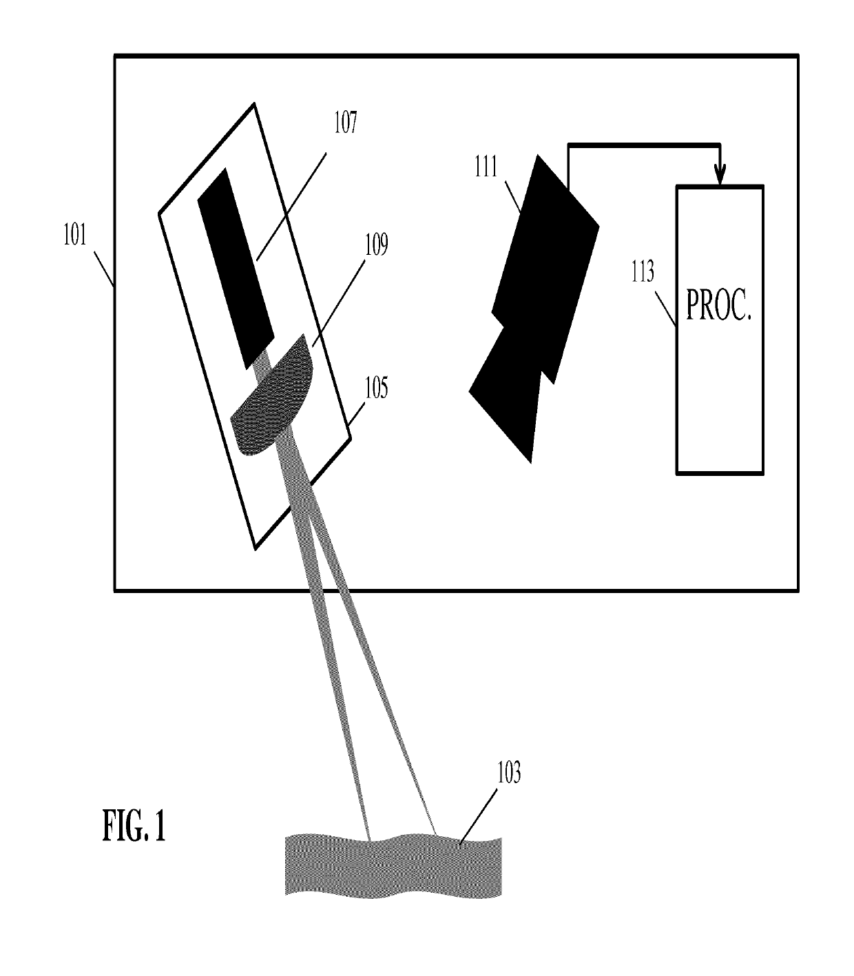
[0010]The invention may allow improved and / or facilitated determination of a propagation velocity for a surface wave in animal tissue. In particular, the inventors have realized that such a propagation velocity can accurately be determined using single camera speckle pattern imaging based on a plurality of light spots and associated speckle patterns. The approach can utilize that when illuminating a rough surface with coherent light, minute path length differences in the reflected field result in interference / speckle patterns that can be observed by a defocused camera. The resulting speckle patterns provide a very strong dependency on even small variations in the surface reflecting the light spot, and the inventors have realized that the analysis of two speckle patterns from two different light spots in images from a single camera can be used to provide a very accurate indication of the propagation of a surface wave in animal tissue.
[0036]The invention may allow an improved determination of a pulse wave velocity and in particular may allow a reduced complexity determination which does not require sensors to be attached to or inserted into the patient, and which further does not require accurate synchronization or complex signal processing.

Problems solved by technology

However, the proposed approaches tend to not be optimal.
For example, they tend to be inconvenient to the test object (e.g. requiring invasive operations), cumbersome to perform, to provide results that are not as accurate or reliable as would be preferred and / or to require complex and / or costly equipment.
Such synchronization tends to be complicated and costly to achieve.

Method used


Image

  • Determining a propagation velocity for a surface wave
  • Determining a propagation velocity for a surface wave
  • Determining a propagation velocity for a surface wave

Examples


Embodiment Construction

[0047]The following description focuses on embodiments for measuring propagation velocity for a surface wave in animal tissue, including human tissue. Specifically, the inventors have realized the approach can be used to determine a propagation velocity for a pulse wave. In particular, the following description will focus on systems which allow an efficient, accurate, reliable, flexible and easy determination of propagation velocity for a pulse wave in a human patient. The system in particular provides measurements that may be very significant for evaluating, detecting and diagnosing many cardio-vascular diseases.

[0048]FIG. 1 illustrates an example of a pulse wave propagation velocity measurement setup in accordance with some embodiments of the invention.

[0049]The setup comprises a speckle imaging apparatus 101 which is arranged to determine the pulse wave propagation velocity by performing speckle imaging from at least two speckle patterns which are projected onto a part of the pat...


PUM


Abstract

An apparatus for determining a propagation velocity for a surface wave comprises a coherent light source (105) for generating at least a first and a second light spot on a surface (103). A camera (111) captures at least one out-of-focus image of at least a part of the surface (103) comprising the light spots. The out-of-focus image comprises light spot image objects for the light spots where the light spot image objects have speckle patterns. An analyzer (113) determines the propagation velocity in response to a time difference between speckle pattern changes in the two speckle patterns. The camera may specifically use a rolling shutter allowing the determination of the propagation velocity to be based on a spatial analysis of the speckle patterns. The approach may in particular allow an efficient remote measuring of pulse wave velocities e.g. in animal tissue and in particular, in human tissue.

Description

FIELD OF THE INVENTION[0001]The invention relates to determination of a propagation velocity for a surface wave e.g. in animal tissue and in particular, but not exclusively, to determining of a propagation velocity for a pulse wave in human tissue. The invention can also be used to estimate other types of wave propagation along the targeted surface, which may find industrial applications, such as vibration monitoring for production equipment.BACKGROUND OF THE INVENTION[0002]The measurement and monitoring of various properties of animal tissue has become of high importance in many fields. Therefore, there is an increasing desire to provide new or improved methods of measuring characteristics of animal (including human) tissue. In particular, there is a desire to provide methods which allow an easy and practical application with the minimum of inconvenience to the test subject. A particular measurement that is of interest is the measurement of a propagation velocity for a surface wave...

Claims


Application Information

Patent Timeline
Patent Type & Authority Patents(United States)
IPC IPC(8): G01P3/36G01B11/16A61B5/00G01B9/02
CPCG01B11/162G01B9/02095A61B5/0059
Inventor MUIJS, REMCO THEODORUS JOHANNESDAMKAT, CHRISDE BRUIJN, FREDERIK JAN
Owner KONINK PHILIPS ELECTRONICS NV
Learn More