Method and apparatus for determining a position of a microphone

a technology for determining the position of a microphone and a microphone body, which is applied in the direction of instruments, stereophonic arrangments, measurement devices, etc., can solve the problems of affecting the accuracy of the measurement, the inability to accurately determine the position of the microphone, and the deviation of the ideal setup of the practical surround sound speaker. to achieve the effect of improving the accuracy

Active Publication Date: 2016-01-28
KONINKLJIJKE PHILIPS NV
View PDF13 Cites 1 Cited by
  • Summary
  • Abstract
  • Description
  • Claims
  • Application Information

AI Technical Summary

Benefits of technology

[0024]The third arrival time estimate may provide a further estimate for the propagation delay from the first speaker to the position in addition to an estimate based on either one of the first and second arrival time estimates. The approach may thus provide multiple estimates of the time of arrival/propagation delay thereby

Problems solved by technology

A particularly important challenge in many applications is that of determining loudspeaker positions for a rendering setup, such as for a surround sound system.
Indeed, a significant inconvenience perceived by consumers when using e.g. home cinema surround sound is the need for a relatively large number of speakers to be positioned at specific positions.
Typically, practical surround sound speaker setups will deviate from the ideal setup due to users finding it impractical to position the speakers at the optimal positions.
The calibration of such systems may take

Method used


Image

  • Method and apparatus for determining a position of a microphone
  • Method and apparatus for determining a position of a microphone
  • Method and apparatus for determining a position of a microphone

Examples


Embodiment Construction

[0061]The following description focuses on embodiments of the invention applicable to a system for determining positions of a microphone for use in a calibration of a spatial audio rendering system. However, it will be appreciated that the invention is not limited to this application but may be applied to many other applications.

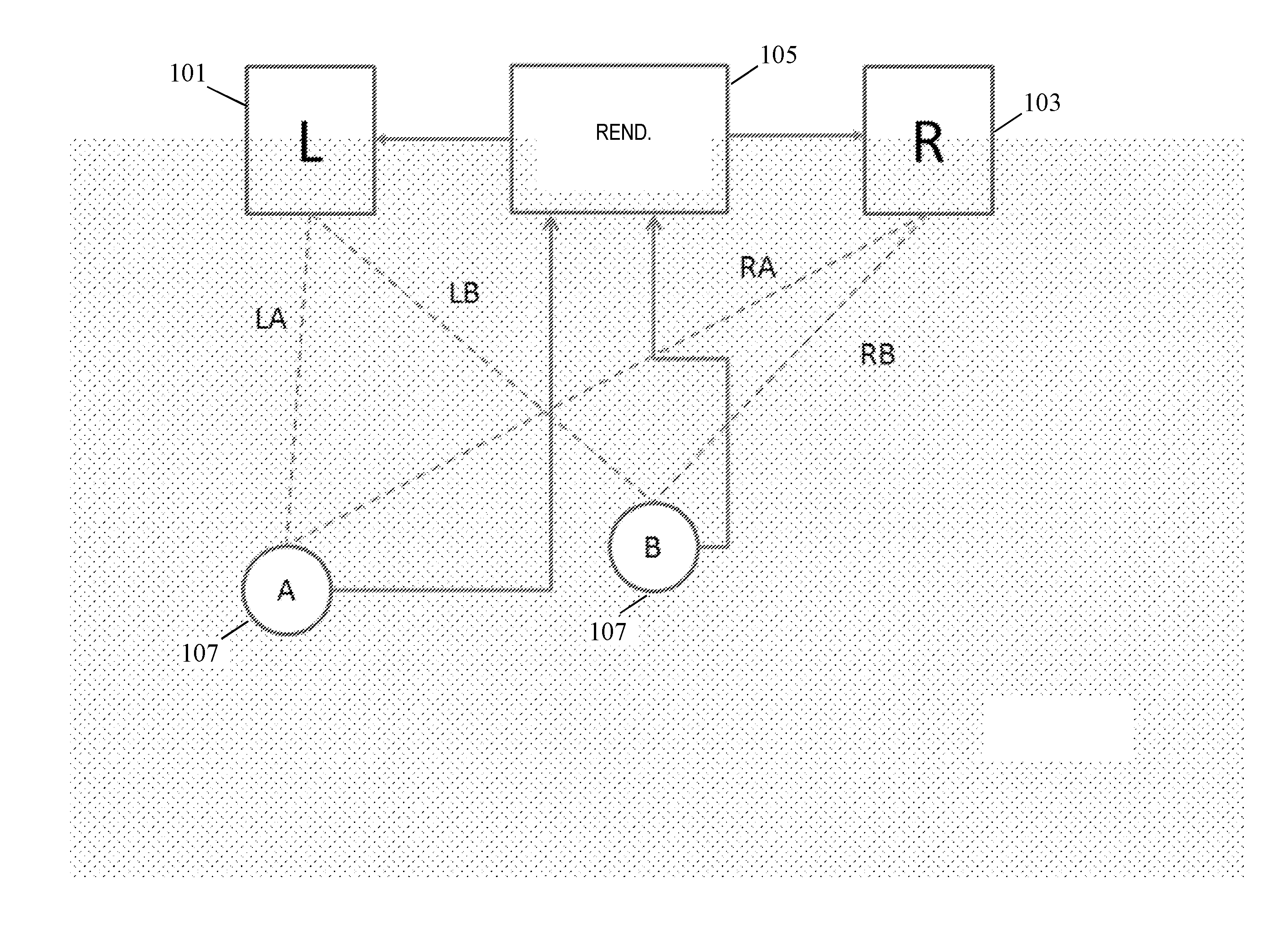
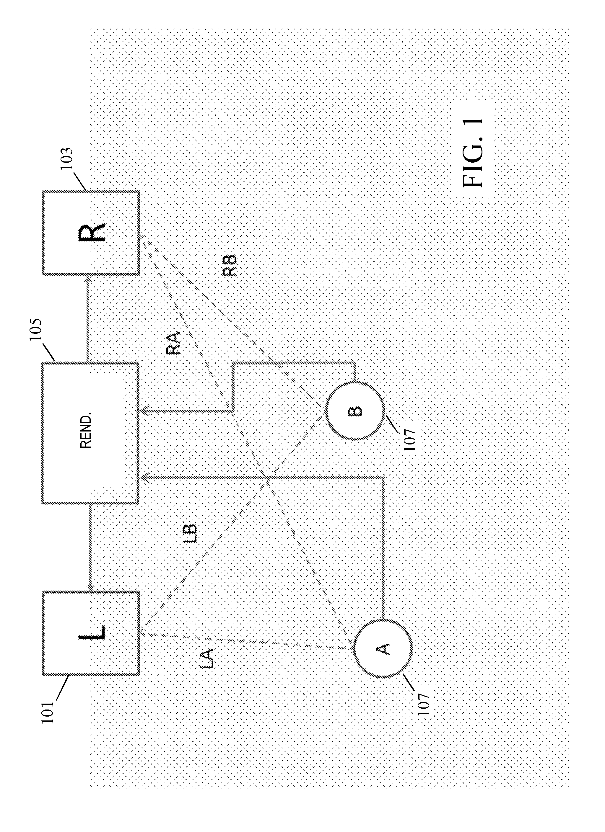
[0062]The following description will focus on a sound rendering arrangement as illustrated in FIG. 1. In the example, the sound rendering arrangement comprises first and second loudspeakers 101, 103. In the specific example, the first and second speakers 101, 103 are speakers of a stereo rendering system, and will also be referred as the left and right speaker respectively.

[0063]In the specific example, the system is a two channel (stereo) rendering system. However, it will be appreciated that in other embodiments the system may be a multi-channel system comprising more than two channels. Specifically, the first and second speaker 101, 103 may be two speaker...


PUM


Abstract

An apparatus comprises a receiver (203) receiving a multichannel signal comprising two channels for rendering by a first speaker (101) at a first position and a second speaker (103) at a second position respectively. A first signal generator (207) generates a correlated signal and a second signal generator (209) generates an uncorrelated signal from the multichannel signal, the signals comprising respectively correlated and uncorrelated signal components for the channels. A receiver (201) receives a microphone signal from the microphone (107). A first correlator (213) determines a first correlation signal from a correlation of the microphone signal and the correlated signal, and a second correlator (215) determines a second correlation signal from a correlation of the microphone signal and the uncorrelated signal. A position estimator (219) estimates a position of the microphone from the first and second correlation signals. For example, timings of peaks in the correlations signals may be used to determine propagation delays and thus distances from the speakers (101, 103).

Description

FIELD OF THE INVENTION[0001]The invention relates to a method and apparatus for determining a position of a microphone, and in particular, but not exclusively, for determining a position of a microphone as part of a speaker calibration operation.BACKGROUND OF THE INVENTION[0002]In recent decades, the variety and flexibility of audio applications has increased immensely with e.g. the variety of audio and capture rendering applications varying substantially. The audio rendering and capture setups are used in diverse acoustic environments and for many different applications.[0003]In many applications it is therefore desirable to be possible to determine the position of a microphone, a listening position or a loudspeaker relative to other loudspeakers. In many applications these issues may be reduced to the same underlying problem, namely that of determining a position of a microphone.[0004]Indeed, in many applications, a listening position may be determined by calibrating the system us...

Claims


Application Information

Patent Timeline
IPC IPC(8): H04S7/00G01S5/28
CPCH04S7/301H04S2400/11H04S2400/01G01S5/28
Inventor HARMA, AKI, SAKARI
Owner KONINKLJIJKE PHILIPS NV
Why Eureka
Try Eureka