
Pluggable module with coaxial connector interface

a plug-in module and coaxial connector technology, applied in the direction of network connectors, couplings/cases, coupling device connections, etc., can solve the problems of inability to elegantly solve the problem of external baluns, add incremental cost and complexity, and use external baluns

Active Publication Date: 2022-01-11
METHODE ELETRONICS INC
View PDF32 Cites 1 Cited by
  • Summary
  • Abstract
  • Description
  • Claims
  • Application Information

AI Technical Summary

Benefits of technology

The invention is a pluggable module that integrates an F-Type connector and a balun to allow for native connectivity to coaxial cable infrastructure. This eliminates the need for an external balun and improves signal integrity and overall improved broadband performance. The invention is compact and integrated into a pluggable module, allowing for better signal integrity and better performance. The invention is novel because it also incorporates all the electronics necessary for a complete Gfast physical layer interface. The invention provides a miniaturized SFP package with components on both sides of the PCB and the balun having surface mount leads for mounting to pads on a first side of the PCB and facilitating mounting of other components on a second side of the PCB.

Problems solved by technology

Such an external balun adds incremental cost and complexity when interfacing between coaxial cable and equipment with a twisted pair interface Additionally the use of an external balun is not an elegant solution because just a standard balun is as big, or indeed bigger, than a pluggable module, such as an SFP.

Method used


Image

  • Pluggable module with coaxial connector interface
  • Pluggable module with coaxial connector interface
  • Pluggable module with coaxial connector interface

Examples


Embodiment Construction

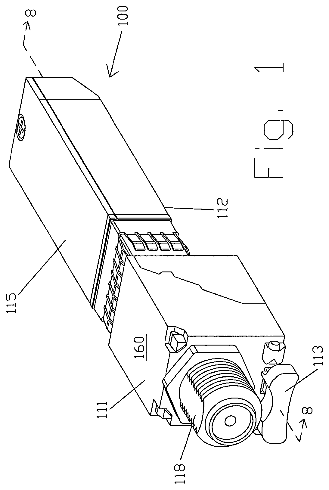
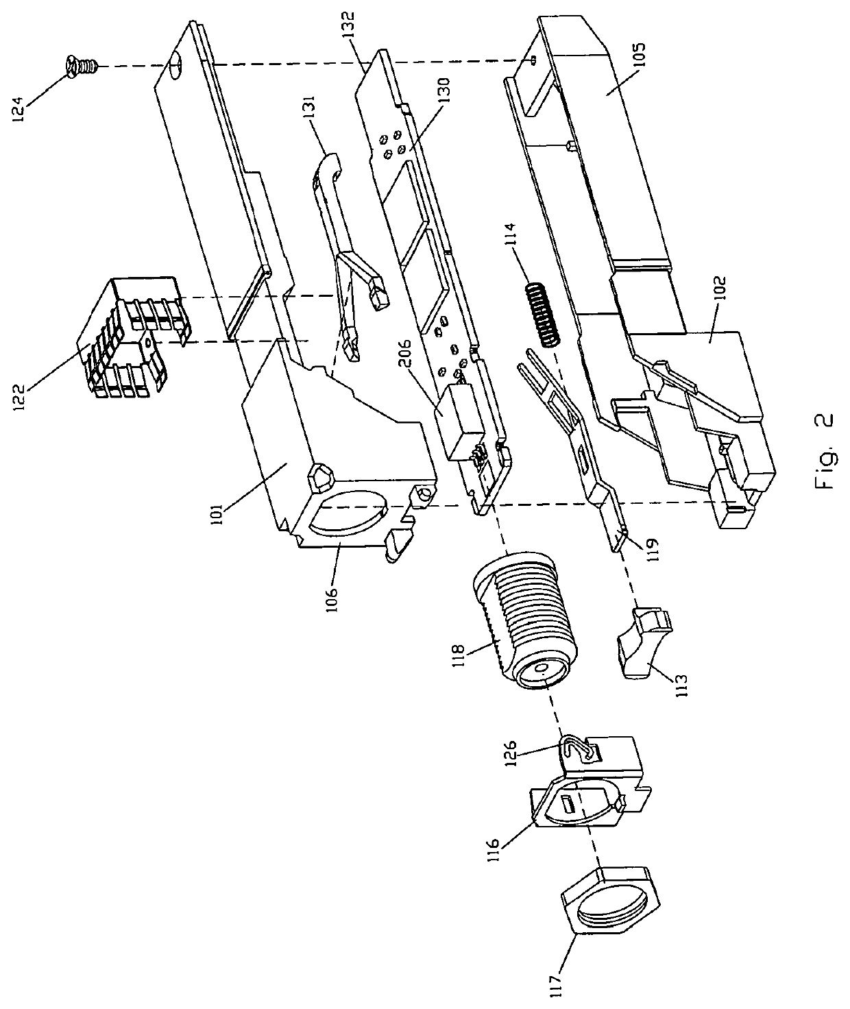
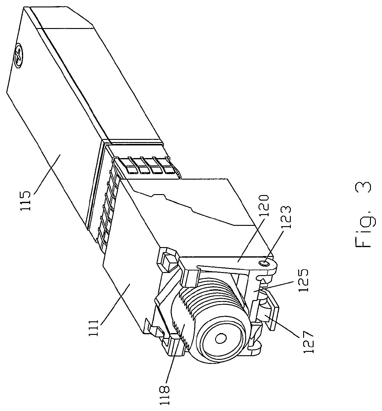
[0038]Embodiments of the Coaxial Module invention are depicted in FIGS. 1-15. In particular, a module having an edge connector at the first end that is compliant with SFP standard SFF-8431 SFP+ specification. The module may have connectors, latching mechanisms and other components, as disclosed in U.S. Pat. Nos. 7,181,173; 8,040,687 and 8,335,088 that are incorporated herein by reference. The second end of the module includes an F-Type coaxial connector as shown in FIGS. 1-5. Such a module is pluggable into a receptacle of a host device, for example, Customer Premise Equipment.

[0039]Turning to FIG. 1 the pluggable module 100 is depicted in an embodiment having a housing top 111, a housing side 112 and a disengager button 113. In an embodiment the housing is compliant SFP and SFP+ specifications, so that front body housing 115 may be inserted into a cage of a host device (not shown) and electric connection is accomplished by an edge connector 132 mating with a corresponding connector...


PUM


Abstract

A pluggable module comprising a housing having a first end and second end, an edge connector disposed at the first end, an F-type coaxial connector at the second end and a release lever including a stamped body that is symmetrical about a centerline bisecting the length of the body.

Description

CROSS REFERENCE TO RELATED APPLICATIONS[0001]The present patent application is a continuation of application Ser. No. 15 / 701,310, filed Sep. 11, 2017, which is incorporated herein by reference.STATEMENT REGARDING FEDERALLY SPONSORED RESEARCH OR DEVELOPMENT[0002]Not ApplicableTHE NAMES OF THE PARTIES TO A JOINT RESEARCH AGREEMENT[0003]Not ApplicableINCORPORATION-BY-REFERENCE OF MATERIAL SUBMITTED ON A COMPACT DISC OR AS A TEXT FILE VIA THE OFFICE ELECTRONIC FILING SYSTEM OFS-WEB)[0004]Not ApplicableSTATEMENT REGARDING PRIOR DISCLOSURES BY THE INVENTOR OR A JOINT INVENTOR[0005]Not ApplicableBACKGROUND OF THE INVENTIONField of the Invention[0006]The present application pertains to the field of high speed communications and in particular, a pluggable module having a coaxial connector interface.Description of Related Art Including Information Disclosed Under 37 CFR 1.97[0007]Not ApplicableBackground[0008]Telecommunications service providers, or carriers, today are focused on the delivery...

Claims


Application Information

Patent Timeline
Patent Type & Authority Patents(United States)
IPC IPC(8): H01R31/06H01R13/46H01R12/70H01R24/54H01R101/00
CPCH01R31/065H01R12/7076H01R13/46H01R24/542H01R2101/00H01R2201/04
Inventor TORRES, LUISLLORENS, JOSEPHPIRILLIS, ALEXANDROSSKEPNEK, ROBERT
Owner METHODE ELETRONICS INC
Learn More