Thermographic examination means and method for non-destructive examination of a near-surface structure at a test object

a near-surface structure and non-destructive technology, applied in the direction of optical radiation measurement, material flaw investigation, instruments, etc., can solve the problems of high cost, noise has a considerable effect on the measurement accuracy of the system, and the measurement method in many cases cannot be employed economically, so as to achieve the effect of easy determination

Active Publication Date: 2022-01-18
FRAUNHOFER GESELLSCHAFT ZUR FOERDERUNG DER ANGEWANDTEN FORSCHUNG EV
View PDF63 Cites 1 Cited by
  • Summary
  • Abstract
  • Description
  • Claims
  • Application Information

AI Technical Summary

Benefits of technology

[0017]During certain times, or at certain points in time following the heat input, the close surroundings may be measured by means of a matrix thermal imaging camera, for example. This involves registering also the time profile of the superficial heat distribution in addition to the location of the heat input. The spatial temperature increase at the individual points of the surroundings around the location of the heat input may be fitted by a suitable function, e.g., by solving the heat equation. Thus, the thermal properties may be inferred even in the event of very defective, or noisy, images and thermography video sequences, or in the event of objects of measurement that are not in a thermally balanced state, e.g., due to heating or cooling. By taking into account the relative behavior with regard to the surroundings that are not directly heated by the heat input, the results may be improved.
[0044]In accordance with an advantageous further development of the invention, the thermographic examination means includes a casting mold for producing a calibration body, in particular a wedge-shaped calibration body. The heat input by means of irradiation is dependent on the spectral and spatial distribution of the power and on the surface area irradiated by the source as well as on the reflection and / or absorption coefficient of the surface. Due to the multitude of influential factors and due to the fact that their magnitudes are sometimes variable or not easy to identify, calibration of the arrangement prior to examining the near-surface structure is advantageous. To this end, a calibration body may be used which has a wedge shape with known thicknesses ranging from the lower to the upper values that can be identified and which has been produced from the same material as the object of measurement. The casting mold provided enables easily producing calibration bodies which correspond to the respective test object.

Problems solved by technology

If a high measurement speed is desired, the technical expenditure and, thus, the costs are so high that this measuring method in many cases cannot be employed economically.
Particularly with very small temperature changes in the order of magnitude of the resolution of the thermal sensor means, noise has a considerable effect on the measurement accuracy of the system.
For a large number of applications, e.g., in the food industry, however, the heat input may be restricted in order to maintain the cold chain.
Due to perspective distortions, for example on account of the optical properties of the thermal sensor means, it is not possible, however, to determine the temperature distribution directly along the surface.
In addition, with inclined and in particular with curved surfaces the problem arises that the size and shape of the surface region to be heated may depend on the inclination and / or curvature of the surfaces, so that the amount of heat specific to the respective surface area also varies.

Method used


Image

  • Thermographic examination means and method for non-destructive examination of a near-surface structure at a test object
  • Thermographic examination means and method for non-destructive examination of a near-surface structure at a test object
  • Thermographic examination means and method for non-destructive examination of a near-surface structure at a test object

Examples


first embodiment

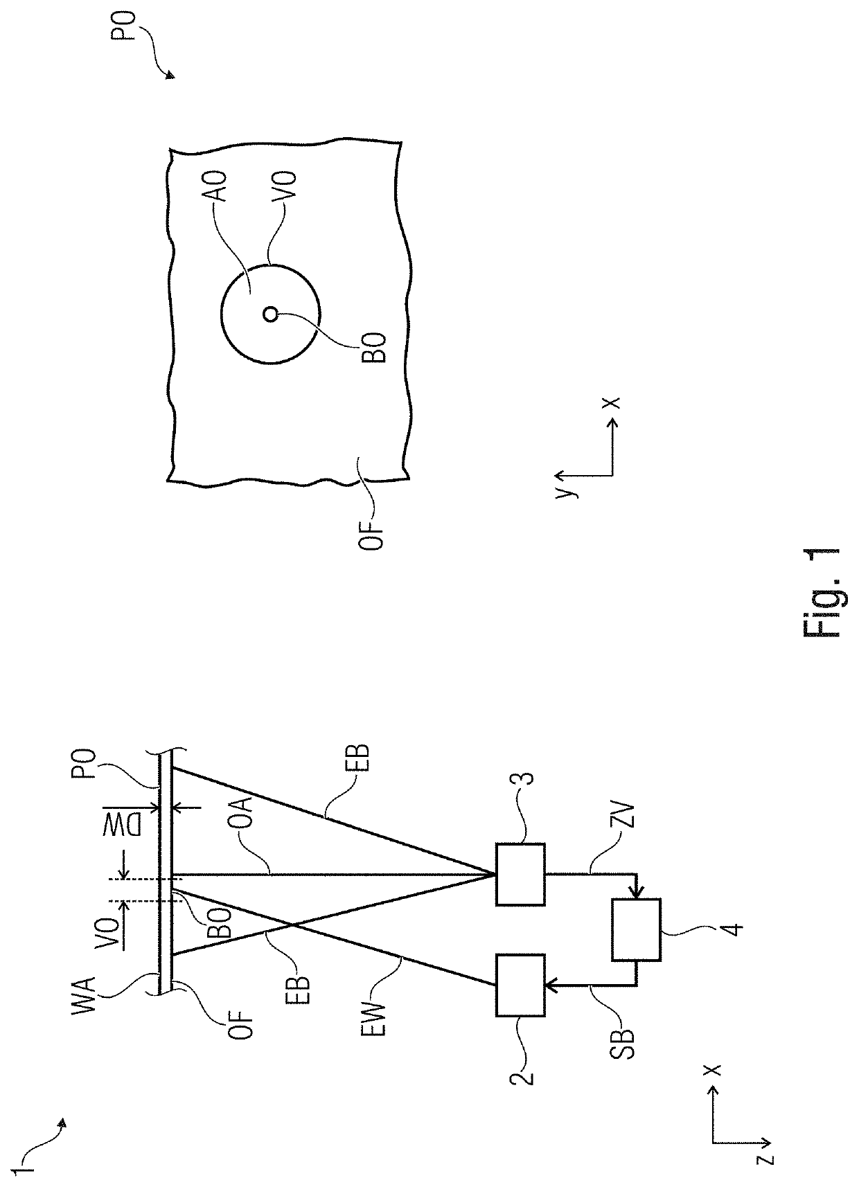
[0060]FIG. 1 shows a schematic top view of an inventive thermographic examination means 1 as well as a pertinent schematic front view of a test object PO in a magnified representation.

[0061]The thermographic examination means 1 includes:

[0062]a heating device 2 for applying heat energy to a surface region to be heated BO of the test object PO;

[0063]a thermal sensor means 3 for detecting a time profile, following the application of heat energy, of a spatial temperature distribution on a surface region to be measured VO of the test object PO, the surface region to be measured VO including the surface region to be heated BO as well as an outer surface region to be measured AO which is adjacent to the surface region to be heated BO; and an evaluation means 4 for evaluating the time profile of the spatial temperature distribution so as to detect at least one parameter DW of the near-surface structure at the surface region to be measured VO.

[0064]In the solutions known from sources [1] to...

second embodiment

[0098]FIG. 5 shows a schematic top view of an inventive thermographic examination means 1 as well as a pertinent schematic front view of a test object PO in a magnified representation.

[0099]In accordance with a particularly advantageous further development of the invention, the heating means 2 is configured to apply heat energy in a simultaneous or time-overlapping manner to several surface regions to be heated BO1, BO2, the thermal sensor means 3 being configured to detect, in a simultaneous or time-overlapping manner, those time profiles of the spatial temperature distributions which follow the application of heat energy, on several surface regions of the test object PO that are to be measured VO1, VO2, the surface regions to be measured VO1, VO2 each including one of the surface regions to be heated BO1, BO2 as well as one outer surface region AO1, AO2 adjacent to the respective surface region to be heated BO1, BO2; and wherein the evaluation means 4 is configured to evaluate the...

third embodiment

[0103]FIG. 6 shows a schematic top view of an inventive thermographic examination means 1 as well as a pertinent schematic front view of a test object PO in a magnified representation. In FIG. 6, the heating device 2, the thermal sensor means 3 and the inclination detection means 6 are depicted to be within one plane. This is only due to reasons related to drawing. In reality, it is more favorable for the heating device 2 and the thermal sensor means 3 to span a first plane, and for the thermal sensor means 3 and the inclination detection means 6 to span a second plane, which planes are arranged at right angles in relation to each other, for example.

[0104]In accordance with an advantageous further development of the invention, the evaluation means 4 is configured to take into account a spatial profile of an inclination NE of the surface region to be measured VO with regard to an optical axis OA of the thermal sensor means 3 in the evaluation of the time profile of the spatial temper...


PUM

PropertyMeasurementUnit
near-surface structureaaaaaaaaaa
heat energyaaaaaaaaaa
spatial temperatureaaaaaaaaaa

Abstract

A thermographic examination device for non-destructive examination of a near-surface structure at a test object includes a heating device for applying heat energy to a surface region to be heated of the test object; a thermal sensor device for detecting a time profile, following the application of heat energy, of a spatial temperature distribution on a surface region to be measured of the test object, the surface region to be measured including the surface region to be heated as well as an outer surface region to be measured which is adjacent to the surface region to be heated; and an evaluator for evaluating the time profile of the spatial temperature distribution so as to detect at least one parameter of the near-surface structure at the surface region to be measured.

Description

CROSS-REFERENCE TO RELATED APPLICATIONS[0001]This application is a continuation of copending International Application No. PCT / EP2015 / 070622, filed Sep. 9, 2015, which is incorporated herein by reference in its entirety, and additionally claims priority from German Application No. DE 102014218136.4, filed Sep. 10, 2014, which is incorporated herein by reference in its entirety.BACKGROUND OF THE INVENTION[0002]When producing parts, in particular parts having small wall thicknesses, it is important for stability and, thus, also for the quality to stick to a defined wall thickness. In particular with methods having a relatively large amount of dispersions, such as lamination, dead-mold casting or centrifugal casting, for example, it is useful to metrologically verify the achieved value on a continuing basis so as to be able to recognize near-surface defects such as delaminations (lamination process), gas inclusions (dead-mold casting) or insufficient wall thicknesses (centrifugal casti...

Claims


Application Information

Patent Timeline
Patent Type & Authority Patents(United States)
IPC IPC(8): G01J5/00G01N25/72G01B21/08G01N9/36
CPCG01N25/72G01B21/085G01N9/36G01J5/00
Inventor DOEGE, JENS
Owner FRAUNHOFER GESELLSCHAFT ZUR FOERDERUNG DER ANGEWANDTEN FORSCHUNG EV
Why Eureka
Try Eureka