Steering control apparatus and steering control method

a control apparatus and control method technology, applied in the direction of electric steering, power driven steering, vehicle components, etc., can solve the problems of reduced motor torque, reduced end-striking impact, and inability to reduce end-striking impact, so as to achieve suitably reduced end-striking impact

Active Publication Date: 2022-01-25
JTEKT CORP +1
View PDF10 Cites 0 Cited by
  • Summary
  • Abstract
  • Description
  • Claims
  • Application Information

AI Technical Summary

Benefits of technology

[0005]The disclosure provides a steering control apparatus and steering control method that are able to suitably reduce an end-striking impact even on a low-μ road.
[0007]With the above configuration, the steering angle limit value is computed so as to reduce when the absolute value of the rotation angle of the rotary shaft exceeds the steering angle threshold, the rotation angle of the rotary shaft being convertible to the wheel steering angle of the steered wheel, and the torque command value that is the target value of the motor torque that the motor outputs is limited to less than or equal to the limit value that is set to the value less than or equal to the steering angle limit value. Thus, for example, when steering is performed to near an end in the case where the steering angle threshold is set to a value near the end, the motor torque is limited, with the result that an end-striking impact is reduced. In addition, with the above configuration, when the absolute value of the rotation angle exceeds the steering angle threshold, the torque command value is computed by reducing the absolute value of the basic command value by using the damping control amount set according to an excess of the angular velocity over the first upper limit angular velocity. Therefore, in the case where the steering angle threshold is set to, for example, near an end, when the steered wheel is on a low-μ road and the wheel steering speed increases, the damping control amount increases, with the result that the motor torque is limited. Therefore, an end-striking impact is suitably reduced.
[0009]With the above configuration, the steering angle limit value is computed by subtracting the angle limiting component and the speed limiting component from the rated torque, so, when the rotation angle exceeds the steering angle threshold, a further increase in the rotation angle is limited, and the steering angle limit value that limits the angular velocity of the rotary shaft is easily computed.
[0010]In the steering control apparatus, an absolute value of the first upper limit angular velocity may be set to higher than an absolute value of the second upper limit angular velocity. Since the angular velocity of the rotary shaft tends to be significantly higher on a low-μ road than on a normal road surface, even when the first upper limit angular velocity is increased, an excess of the angular velocity over the first upper limit angular velocity arises, and the damping control amount that reduces the absolute value of the basic command value is computed. Therefore, as in the case of the above configuration, when the first upper limit angular velocity is set to higher than the second upper limit angular velocity, an end-striking impact is suitably reduced on a low-μ road, and influence on a steering feeling caused by an unnecessary reduction of the absolute value of the basic command value on a road other than the low-μ road is reduced.

Problems solved by technology

For this reason, even when the current command value is limited to less than or equal to the limit value as in the case of the above configuration, the inertia of turn may not sufficiently attenuate, with the result that an end-striking impact may not be reduced.
Thus, for example, when steering is performed to near an end in the case where the steering angle threshold is set to a value near the end, the motor torque is limited, with the result that an end-striking impact is reduced.
Therefore, in the case where the steering angle threshold is set to, for example, near an end, when the steered wheel is on a low-μ road and the wheel steering speed increases, the damping control amount increases, with the result that the motor torque is limited.

Method used


Image

  • Steering control apparatus and steering control method
  • Steering control apparatus and steering control method
  • Steering control apparatus and steering control method

Examples


Embodiment Construction

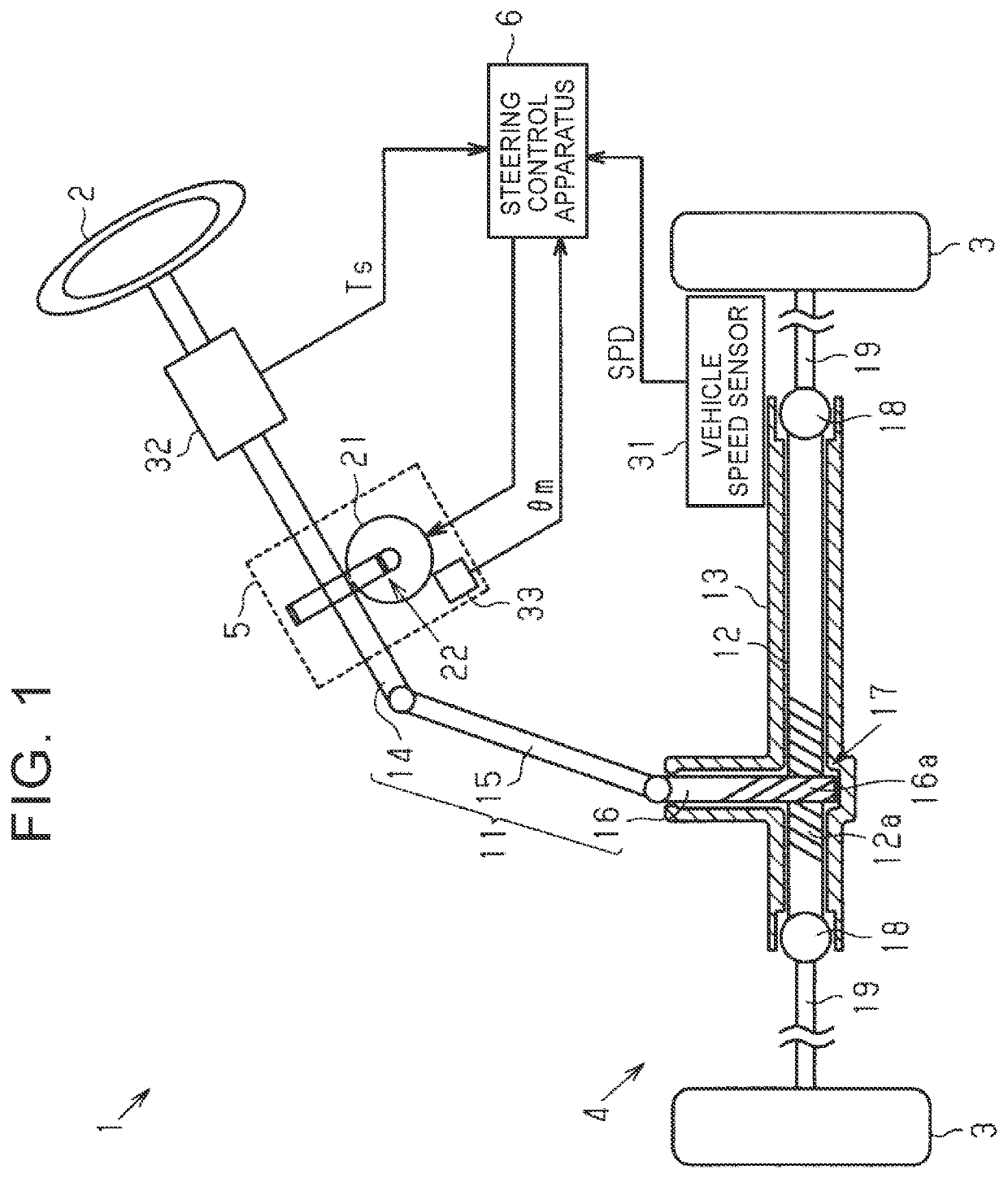
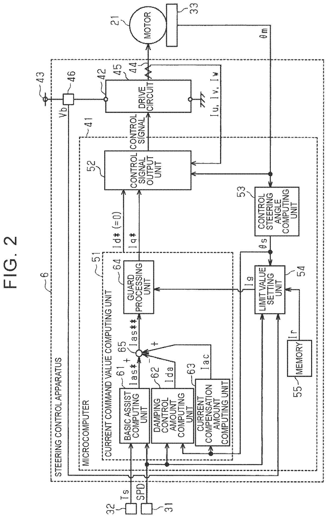
[0021]Hereinafter, an embodiment of a steering control apparatus will be described with reference to the accompanying drawings. As shown in FIG. 1, an electric power steering (EPS) 1 that serves as a steering system that is a controlled object includes a steering mechanism 4. The steering mechanism 4 turns steered wheels 3 based on driver's operation of a steering wheel 2. The EPS 1 includes an EPS actuator 5 and a steering control apparatus 6. The EPS actuator 5 serves as an actuator that applies assist force for assisting in steering operation to the steering mechanism 4. The steering control apparatus 6 controls the operation of the EPS actuator 5.

[0022]The steering mechanism 4 includes a steering shaft 11, a rack shaft 12, and a substantially cylindrical rack housing 13. The steering wheel 2 is fixed to the steering shaft 11. The rack shaft 12 serves as a wheel turning shaft that reciprocates in an axial direction with the rotation of the steering shaft 11. The rack shaft 12 is ...


PUM


Abstract

A steering control apparatus for a steering system includes a controller. The controller sets a limit value to less than or equal to a steering angle limit value, the limit value being an upper limit of an absolute value of a torque command value, and controls a motor such that a motor torque follows the torque command. When the absolute value of a rotation angle of a rotary shaft exceeds a steering angle threshold, the controller computes a damping control amount such that the damping control amount increases with an increase in an excess of an angular velocity of the rotary shaft over a first upper limit angular velocity. The controller computes the torque command value based on a value obtained by combining the basic command value and the damping control amount such that an absolute value of the basic command value is reduced.

Description

INCORPORATION BY REFERENCE[0001]The disclosure of Japanese Patent Application No. 2018-130197 filed on Jul. 9, 2018 including the specification, drawings and abstract is incorporated herein by reference in its entirety.BACKGROUND1. Technical Field[0002]The disclosure relates to a steering control apparatus and a steering control method.2. Description of Related Art[0003]An electric power steering (EPS) including an actuator that uses a motor as a drive source is known as a vehicle steering system. Some of such EPSs acquire a steering angle of a steering wheel (a wheel steering angle of steered wheels) in absolute angle including a range over 360°, and execute various control based on the steering angle. For example, Japanese Patent No. 5962881 (JP 5962881 B) describes a system that, before a rack end that is an end of a rack shaft strikes a rack housing, reduces an impact caused by striking of the rack end (hereinafter, referred to as end-striking impact) by limiting a current comma...

Claims


Application Information

Patent Timeline
Patent Type & Authority Patents(United States)
IPC IPC(8): B62D6/00B62D5/04B62D15/02
CPCB62D5/0469B62D5/0409B62D5/0463B62D15/022B62D5/046
Inventor TOKO, TAKAHIROKATAOKA, NOBUAKIEZAKI, YUKINOBU
Owner JTEKT CORP
Why Eureka
Try Eureka