

Cloward-style cervical mesh cage with lateral stabilizers
a mesh cage and lateral stabilizer technology, applied in the field of cloward-style cage devices for anterior cervical fusion and fixation, can solve problems such as unsatisfactory fixation strength, and achieve the effect of reducing the risk of subsidence and reducing the likelihood of bone plug loosening
- Summary
- Abstract
- Description
- Claims
- Application Information
AI Technical Summary
Benefits of technology
Problems solved by technology
Method used
Image

Examples
first embodiment
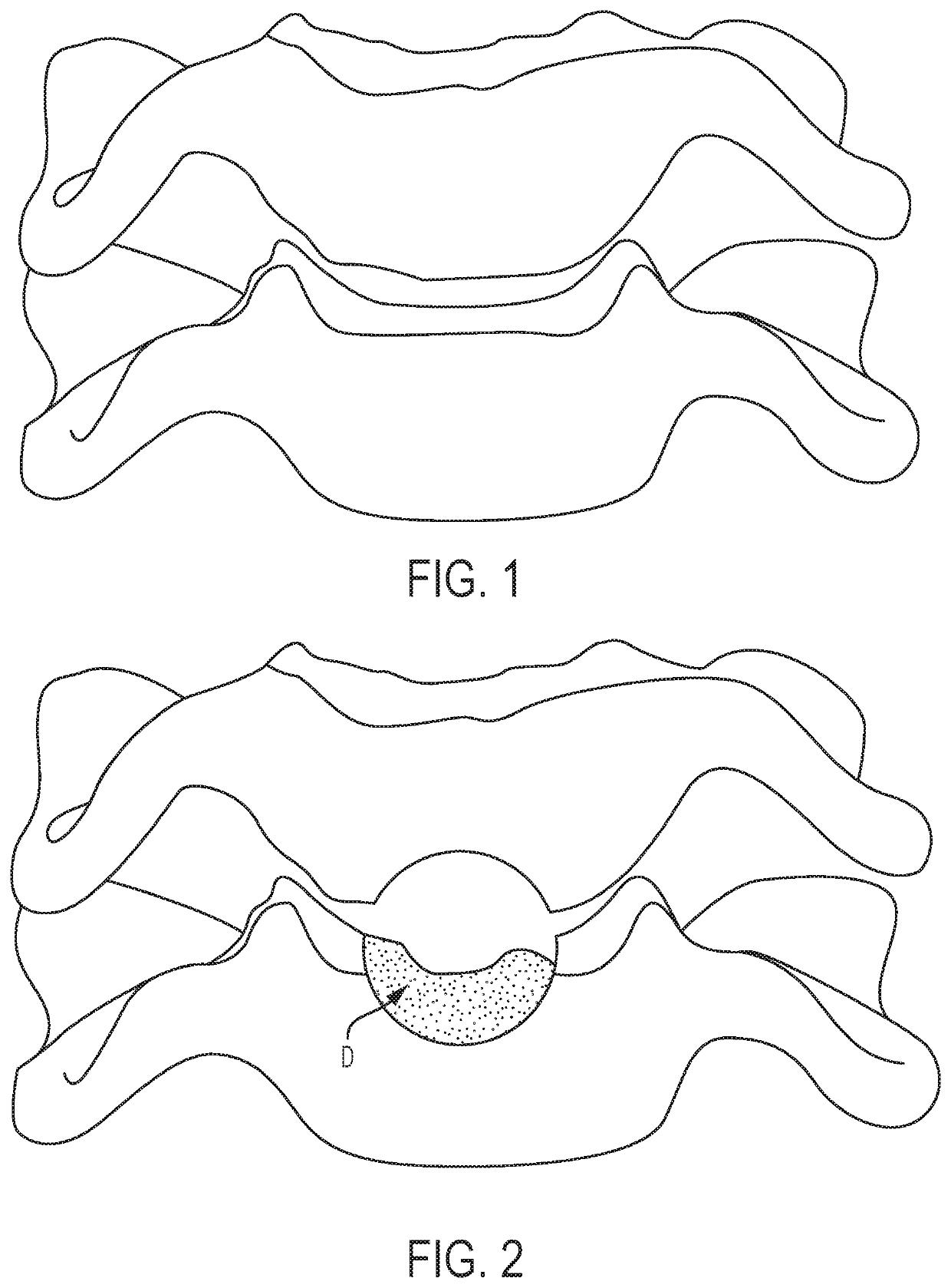
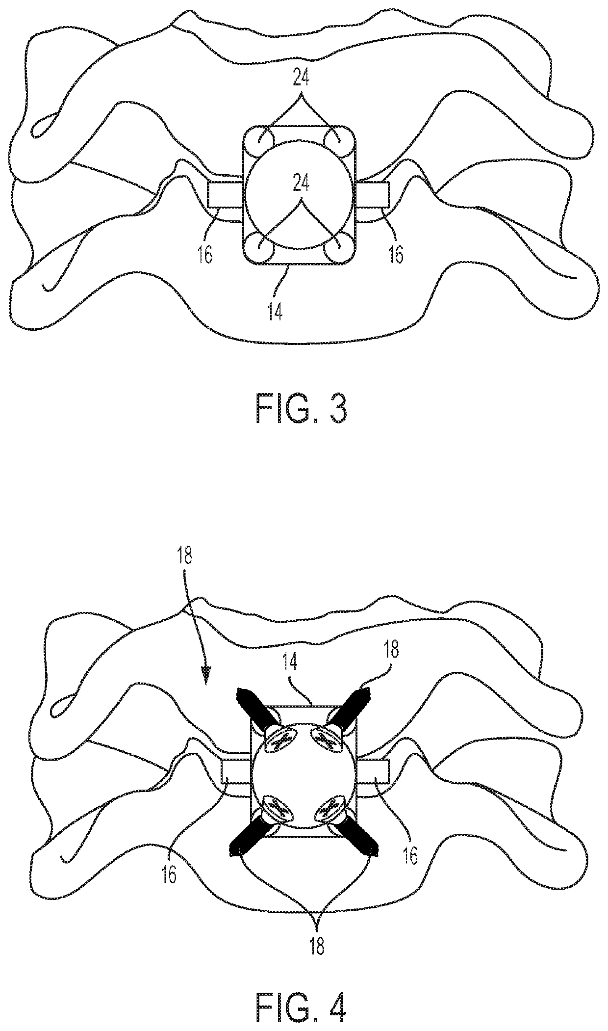
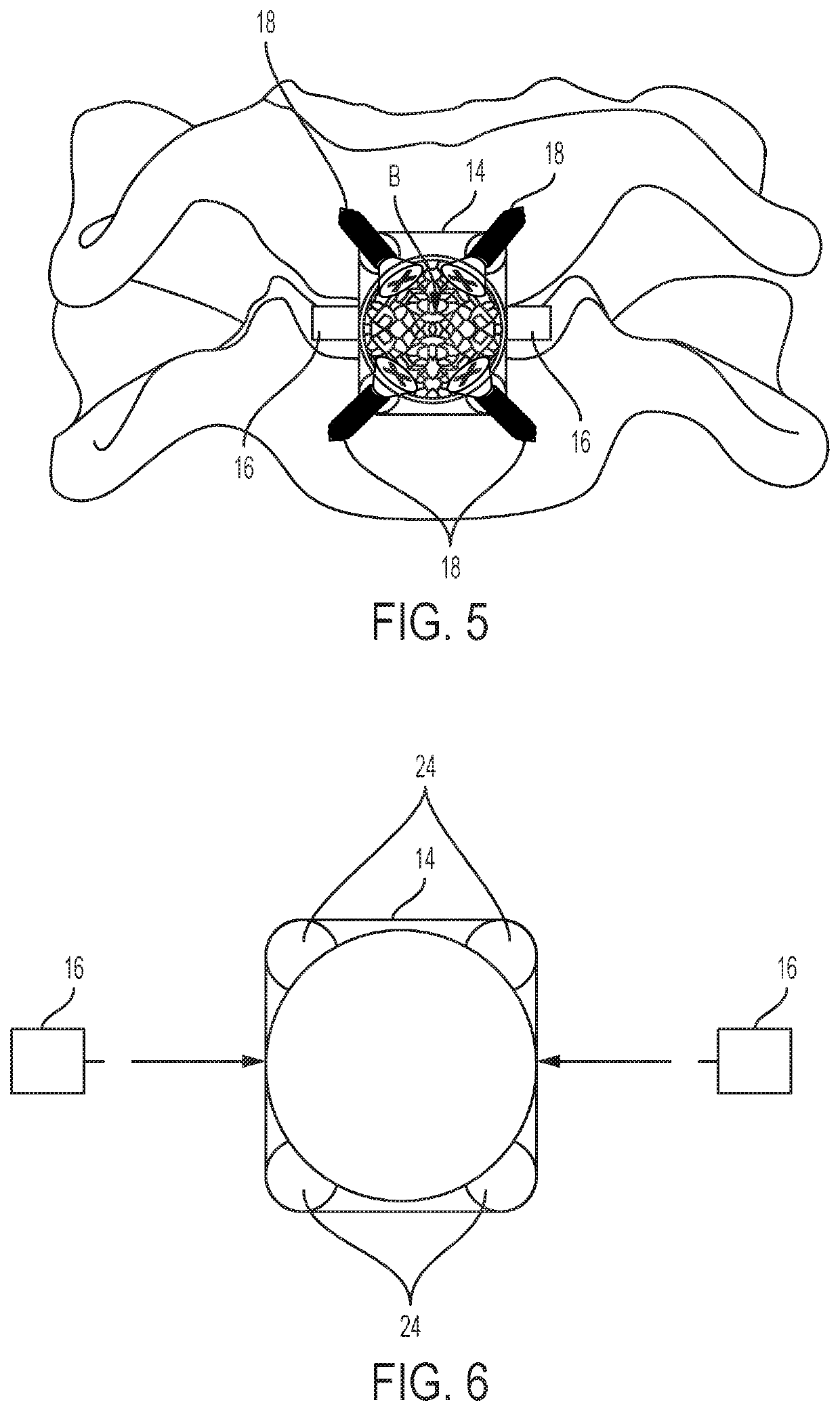
[0038]Referring to FIGS. 2-8, an embodiment of a Cloward-style cervical mesh cage device 10 or plate cage is configured to reduce compression of a patient's interbody cervical bones, also known as the interbody discs or endplates. FIG. 2 shows interbody cervical bones, wherein a cylindrical drill bit has removed bone to allow for a satisfactory decompression of midline compression and foraminal disease. The current embodiment of the device 10 is further configured to fit within a defect D formed in the patient's interbody cervical bones, as further described below and shown in FIG. 2. The device 10 includes a cylindrical body 12, an endplate 14, and a lateral stabilizer, and can include fasteners 18. As seen in FIG. 3, for example, the lateral stabilizer can be a pair of lateral stabilizers 16, where each member of the pair of lateral stabilizers 16 can be located on substantially opposite sides of the body 12. The body 12 is a generally hollow cylindrical body 12 having a proximal ...
second embodiment
[0050]Another embodiment of the Cloward-style mesh cage device 30 is shown in FIGS. 9-15. The cage device 30 includes a cylindrical body 32 formed of a top portion 34 and a bottom portion 36, and an endplate 38, and can further include a wedge insert 40. In the current embodiment, the wedge insert 40 can be included and, when included, is a pair of strut spacers, as further described below. Each of the top portion 34 and bottom portion 36 has a clamshell-like shape, such that the top portion 34 and the bottom portion 36 can be joined at a joint face 42 of each top portion 34 and bottom portion 36 to form a cylindrical-like shape, such as described above.
[0051]The endplate 38 is configured to be formed of a top endplate 44 and a bottom endplate 46, each of which are respectively fixed to the top portion 34 and bottom portion 36 of the cylindrical body 32. The endplate 38 is configured to be adjacent to an anterior face of the cervical bones when the cylindrical body 32 is in the defe...
third embodiment
[0059]Still another embodiment of the Cloward-style mesh cage device 60 is shown in FIGS. 16 and 17. The cage device 60 is similar to the cage device 30 of FIGS. 9-15, as described above, including a cylindrical body 62 formed of a top portion 64 and a bottom portion 66, and can include a pair of strut spacers. However, the cage device 60 is configured to fit entirely within the defect D. Thus, the cage device 60 lacks an endplate that is configured to be adjacent to an anterior face of the cervical bones. Each of the top portion 64 and bottom portion 66 has a clamshell-like shape, such that the top portion 64 and the bottom portion 66 can be joined at a joint face 68 of each top portion 64 and bottom portion 66 to form a cylindrical-like shape, such as described above. Thus, the top portion 64 and bottom portion 66 form lateral stabilizers having joint faces, as described above. The lateral stabilizers can be removable or fixed to the cylindrical body 62. Furthermore, the cylindric...
PUM
 Abstract
Description
Claims
Application Information