Supercharge Your Innovation With Domain-Expert AI Agents!

Collision avoidance apparatus

a technology of collision avoidance and apparatus, which is applied in the direction of traffic control systems, transportation and packaging, instruments, etc., can solve problems such as concerns about worsening riding comfor

Active Publication Date: 2022-02-01
MITSUBISHI ELECTRIC CORP
View PDF24 Cites 1 Cited by
  • Summary
  • Abstract
  • Description
  • Claims
  • Application Information

AI Technical Summary

Benefits of technology

The present invention provides a collision avoidance apparatus that can prevent collisions through both steering and braking. The apparatus includes a no-entry zone, a following determination unit, a constraint establishing unit, an evaluation function setting unit, a solution computing unit, a vehicle state quantity predictor, and a target value computing unit. The apparatus can predict the future movement of the vehicle based on obstacle information and lane information, and evaluate the accuracy of the predicted movement. The solution computing unit will then compute a solution to improve the accuracy of the predicted movement. The vehicle state quantity predictor will then predict the future movement of the vehicle based on the solution and the predicted value of the state quantity. The target value computing unit will then compute the target value of each actuator that controls the steering and acceleration / deceleration of the vehicle based on the solution and the predicted value of the state quantity. This invention prevents worsening of riding comfort caused by switching between steering and braking for avoiding collisions.

Problems solved by technology

Such switching creates concerns about worsening the riding comfort.

Method used


Image

  • Collision avoidance apparatus
  • Collision avoidance apparatus
  • Collision avoidance apparatus

Examples


embodiment 1

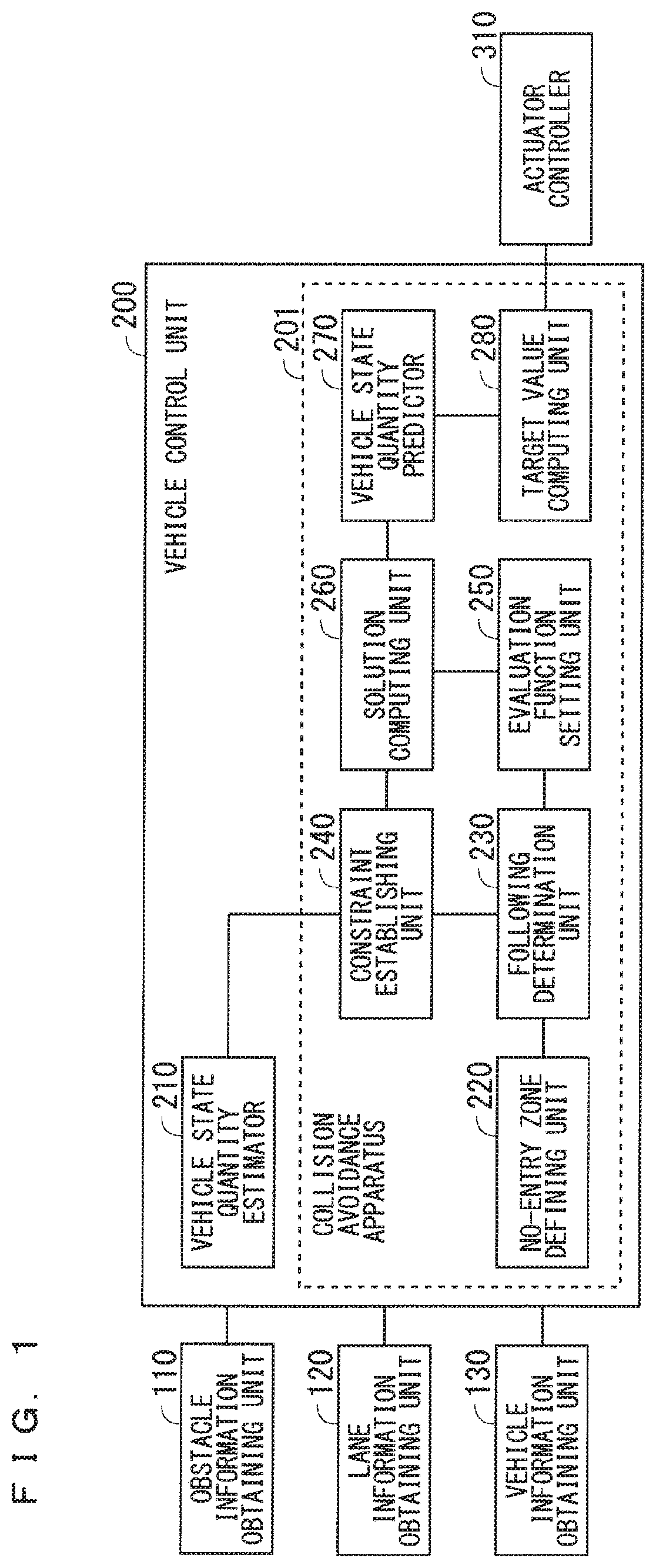
[0024]FIG. 1 is a block diagram illustrating a schematic configuration of a collision avoidance system according to Embodiment 1 of the present invention. The collision avoidance system is mounted on a vehicle, and includes a vehicle control unit 200, and an obstacle information obtaining unit 110, a lane information obtaining unit 120, a vehicle information obtaining unit 130, and an actuator controller 310 each of which is connected to the vehicle control unit 200.

[0025]The vehicle control unit 200 controls the overall operations of a vehicle on which the collision avoidance system is mounted (hereinafter referred to as a “subject vehicle”). The vehicle control unit 200 is, for example, an advanced driver-assistance systems Electronic Control Unit (ADAS-ECU).

[0026]The obstacle information obtaining unit 110 obtains obstacle information including information on a position of an obstacle around the subject vehicle. The obstacle information obtaining unit 110 is, for example, a forwa...

embodiment 2

[0129]In Embodiment 1, the following determination unit 230 determines whether an obstacle is an avoidance target or a following target (a following determination), depending on whether the no-entry zone Ao corresponding to the obstacle has overlaps with both of the no-entry zones AR and AL corresponding to the right and left dividing lines. In Embodiment 2, hysteresis is applied to the following determination so that a result of the following determination does not cause hunting. The configuration and the basic operations of a collision avoidance system according to Embodiment 2 are identical to those according to Embodiment 1. Thus, the overlap with the description of Embodiment 1 will be omitted.

[0130]To apply hysteresis to the following determination according to Embodiment 2, the no-entry zone defining unit 220 defines, for an obstacle, a zone for following determination (hereinafter referred to as a “following determination zone”). FIG. 15 illustrates a method for defining a f...


PUM


Abstract

Provided is a collision avoidance apparatus that can avoid a collision through both steering and braking. In a collision avoidance apparatus, a no-entry zone defining unit defines a no-entry zone for preventing a subject vehicle from colliding with an obstacle around the subject vehicle, based on obstacle information including information on a position of the obstacle and based on lane information that is information on a traveling lane of the subject vehicle. A following determination unit determines whether the obstacle is an avoidance target or a following target, based on the position of the obstacle or a position of the no-entry zone. A constraint establishing unit establishes a constraint on a state quantity or a control input of the subject vehicle to prevent the subject vehicle from at least entering the no-entry zone.

Description

BACKGROUND OF THE INVENTIONField of the Invention[0001]The present invention relates to a collision avoidance apparatus for a vehicle.Description of the Background Art[0002]Various collision avoidance apparatuses have been proposed which detect an obstacle in a road on which a subject vehicle is traveling and make the subject vehicle avoid the obstacle by automatically steering the subject vehicle. For example, the collision avoidance apparatus disclosed in Japanese Patent Application Laid-Open No. 2007-253745 sets an evaluation function based on a position of an obstacle, a road boundary, a predicted travel path of the subject vehicle, and a predicted attitude angle and a target attitude angle of the subject vehicle after avoiding the obstacle, and controls the subject vehicle so that the subject vehicle will follow the predicted travel path with which the output value of the evaluation function is the smallest to make the subject vehicle avoid the obstacle. This evaluation functio...

Claims


Application Information

Patent Timeline
Patent Type & Authority Patents(United States)
IPC IPC(8): B60W30/09B60W10/02B60W10/20B60W30/18G08G1/16
CPCB60W30/09B60W10/02B60W10/20B60W30/18G08G1/166B60W2554/00B60W2554/801B60W2710/20B60W2720/106B60W30/095B60W2520/10B60W2520/105B60W2540/18B60W2552/53B60W60/00272B60W30/16B60W2554/802B60W2554/804B60W30/0956G08G1/163
Inventor TOMINAGA, KENTAUNO, TOMOKIKAMEOKA, SHOTAENDO, MASAYA
Owner MITSUBISHI ELECTRIC CORP
Features
  • R&D
  • Intellectual Property
  • Life Sciences
  • Materials
  • Tech Scout
  • Unparalleled Data Quality
  • Higher Quality Content
  • 60% Fewer Hallucinations
Learn More