Flame-shaped chip and flameless candle
a chip and flameless technology, applied in the field of decorative lighting, can solve the problems of affecting the overall appearance of the candle, great space for improvement, etc., and achieve the effects of improving the overall appearance, good candle simulation effect, and easy assembly and disassembly
- Summary
- Abstract
- Description
- Claims
- Application Information
AI Technical Summary
Benefits of technology
Problems solved by technology
Method used
Image
Examples
example 1
[0031]This example describes the invention when the needle serves as the fulcrum for swinging of the flame-shaped chip by way of lower support.
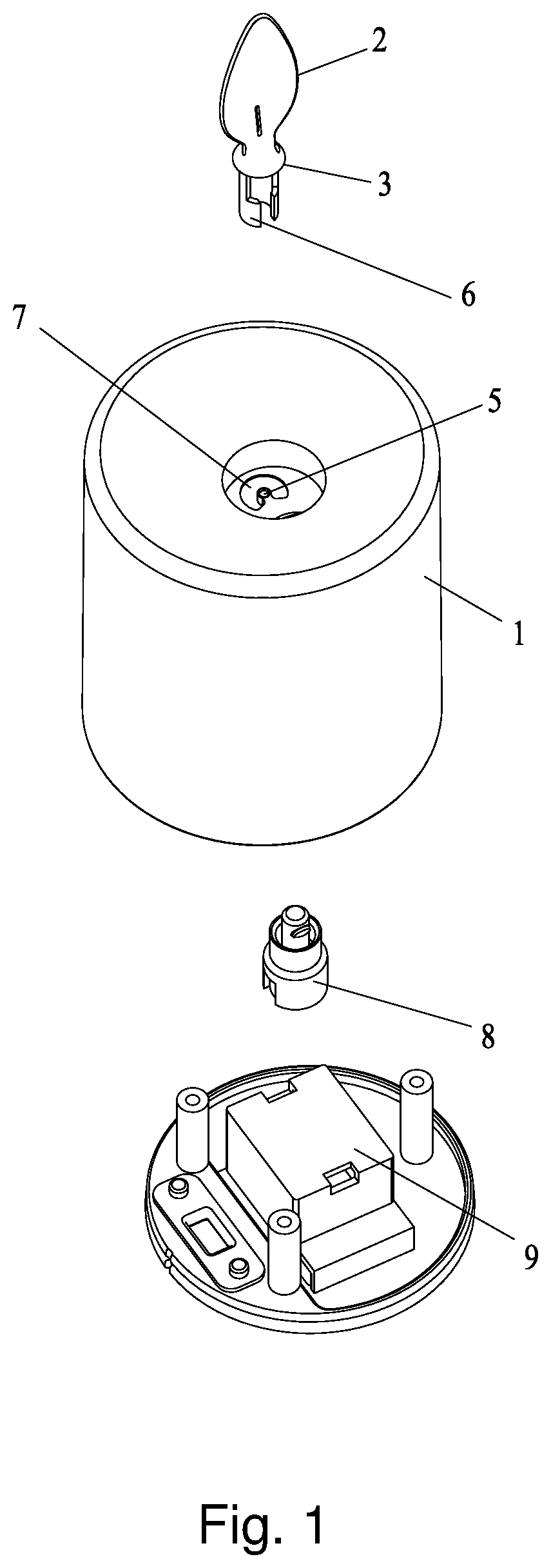
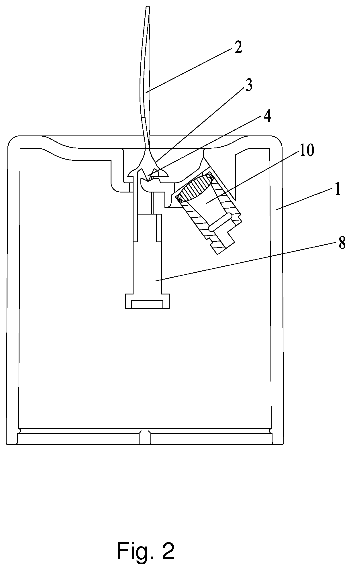
[0032]As shown in FIG. 1 and FIG. 2, the invention of flameless candle comprises of a flame-shaped chip and candle-shaped housing, wherein the flame-shaped chip includes an upper flame-shaped piece (2), an umbrella (3) and a needle (4). The umbrella (4) is arranged at the bottom of the upper flame-shaped piece (2) and used for covering, and the needle (4) is arranged in the umbrella (4) as the umbrella rod. The needle (4) and the umbrella (3) are integrally or separately arranged. The needle (4) is big end up or vice versa. The thinner end serves as the fulcrum for swinging of the flame-shaped chip by contacting with the top end face of the housing (1). The highest point of the needle (4) is higher than the lowest point of the top end face of the housing (1). The upper piece (2) and the umbrella (3) are combined with the housing (1) from the ...
example 2
[0038]This example describes the invention when the needle serves as the fulcrum for swinging of the flame-shaped chip by way of upper support.
[0039]As shown in FIG. 3 and FIG. 4, the invention of flameless candle comprises of a flame-shaped chip and candle-shaped housing, wherein the flame-shaped chip includes an upper flame-shaped piece (2), an umbrella (3) and a needle (4). The umbrella (4) is arranged at the bottom of the upper flame-shaped piece (2) and used for covering, and the needle (4) is arranged in the umbrella (4) as the umbrella rod. The needle (4) and the umbrella (3) are separately arranged, and the needle (4) is arranged on the top end face of the housing (1). The needle (4) is thinner end up and the thinner end serves as the fulcrum for swinging of the flame-shaped chip. The highest point of the needle (4) is higher than the lowest point of the top end face of the housing (1). The upper piece (2) and the umbrella (3) are combined with the housing (1) from the upper...
example 3
[0045]The difference between this example and example 1 only lies in that: the structure of swinging mechanism is different.
[0046]The swinging mechanism may be structured in one of the following ways:
[0047](1) The driving device is a rotary disc, which is driven to horizontally rotate by a transmission shaft or a drive unit. The rotary disc is provided with a lever for triggering the driven device. The drive unit is arranged in the housing;
[0048](2) The driving device is a rotary column, which is driven to horizontally rotate by a transmission shaft or a drive unit and used for touching the driven device. The drive unit is arranged in the housing;
[0049](3) The driving device is a fan, and an air outlet of the fan is arranged at the bottom of the driven device;
[0050](4) The bottom of the driven device is provided with a magnet, and the driving device is a primary magnet device. The primary magnet device comprises a link piece, an upper magnet, a lower magnet, and an induction coil, w...
PUM
 Abstract
Description
Claims
Application Information
 - R&D
- Intellectual Property
- Life Sciences
- Materials
- Tech Scout
- Unparalleled Data Quality
- Higher Quality Content
- 60% Fewer Hallucinations
Browse by: Latest US Patents, China's latest patents, Technical Efficacy Thesaurus, Application Domain, Technology Topic, Popular Technical Reports.
© 2025 PatSnap. All rights reserved.Legal|Privacy policy|Modern Slavery Act Transparency Statement|Sitemap|About US| Contact US: help@patsnap.com


