
Lifting device for additive manufacturing and operational method thereof

a lifting device and additive manufacturing technology, applied in the direction of additive manufacturing, manufacturing tools, additive manufacturing, etc., can solve the problems of inconvenient subsequent assembly, disassembly, maintenance, and high energy consumption, so as to reduce the processing space and the powder feeding space, reduce the loss of powders, and reduce the printing area

Inactive Publication Date: 2020-02-27
TONG-TAI MASCH & TOOL CO LTD
View PDF0 Cites 1 Cited by
  • Summary
  • Abstract
  • Description
  • Claims
  • Application Information

AI Technical Summary

Benefits of technology

The lifting device in this patent allows for the simultaneous movement of both the processing base and the powder feeding base through a single power source. This results in a smaller processing chamber size and reduces the space required for processing and powder feeding. Additionally, it is easier to assemble, disassemble, and maintain. Overall, this device improves the efficiency and convenience of additive manufacturing.

Problems solved by technology

However, operation of controlling two power sources is complicated and the energy consumption is high.
It is inconvenient for subsequent assembly, dis-assembly, and maintenance.

Method used


Image

  • Lifting device for additive manufacturing and operational method thereof
  • Lifting device for additive manufacturing and operational method thereof
  • Lifting device for additive manufacturing and operational method thereof

Examples


Embodiment Construction

[0022]The structure and the technical means adopted by the present disclosure to achieve the above and other objects can be best understood by referring to the following detailed description of the preferred embodiments and the accompanying drawings. Furthermore, directional terms described by the present disclosure, such as upper, lower, front, back, left, right, inner, outer, side, longitudinal / vertical, transverse / horizontal, etc., are only directions by referring to the accompanying drawings, and thus the used directional terms are used to describe and understand the present disclosure, but the present disclosure is not limited thereto.

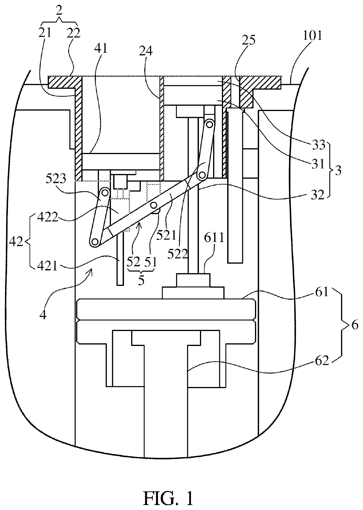
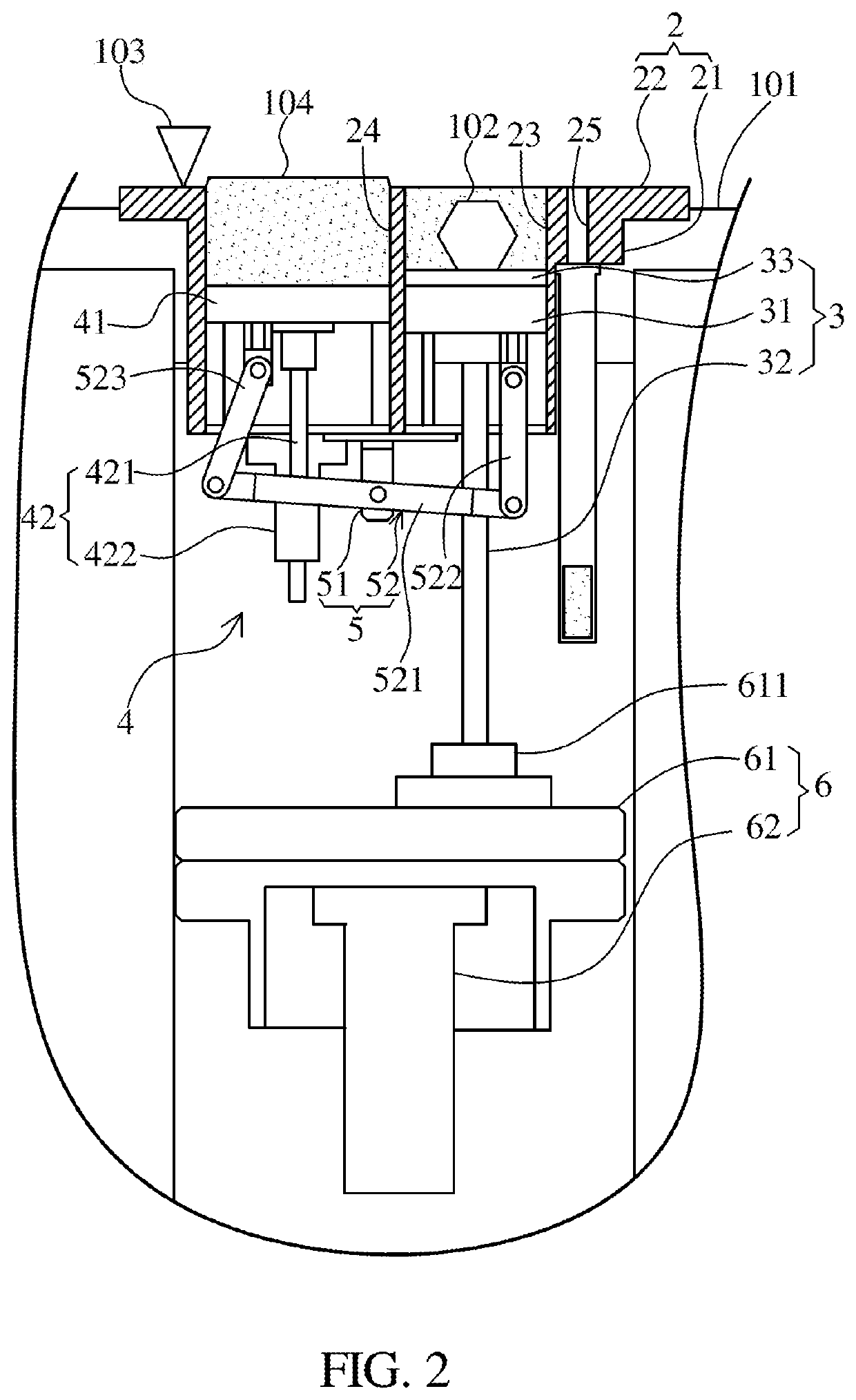
[0023]Referring to FIGS. 1 and 2, a lifting device for additive manufacturing according to the preferred embodiment of the present disclosure is illustrated, wherein the lifting device is disposed in a processing chamber 101 of a three-dimensional printing equipment for additive manufacturing and comprises a base 2, a processing module 3, a powder...


PUM

PropertyMeasurementUnit
lengthaaaaaaaaaa
sizeaaaaaaaaaa
structureaaaaaaaaaa

Abstract

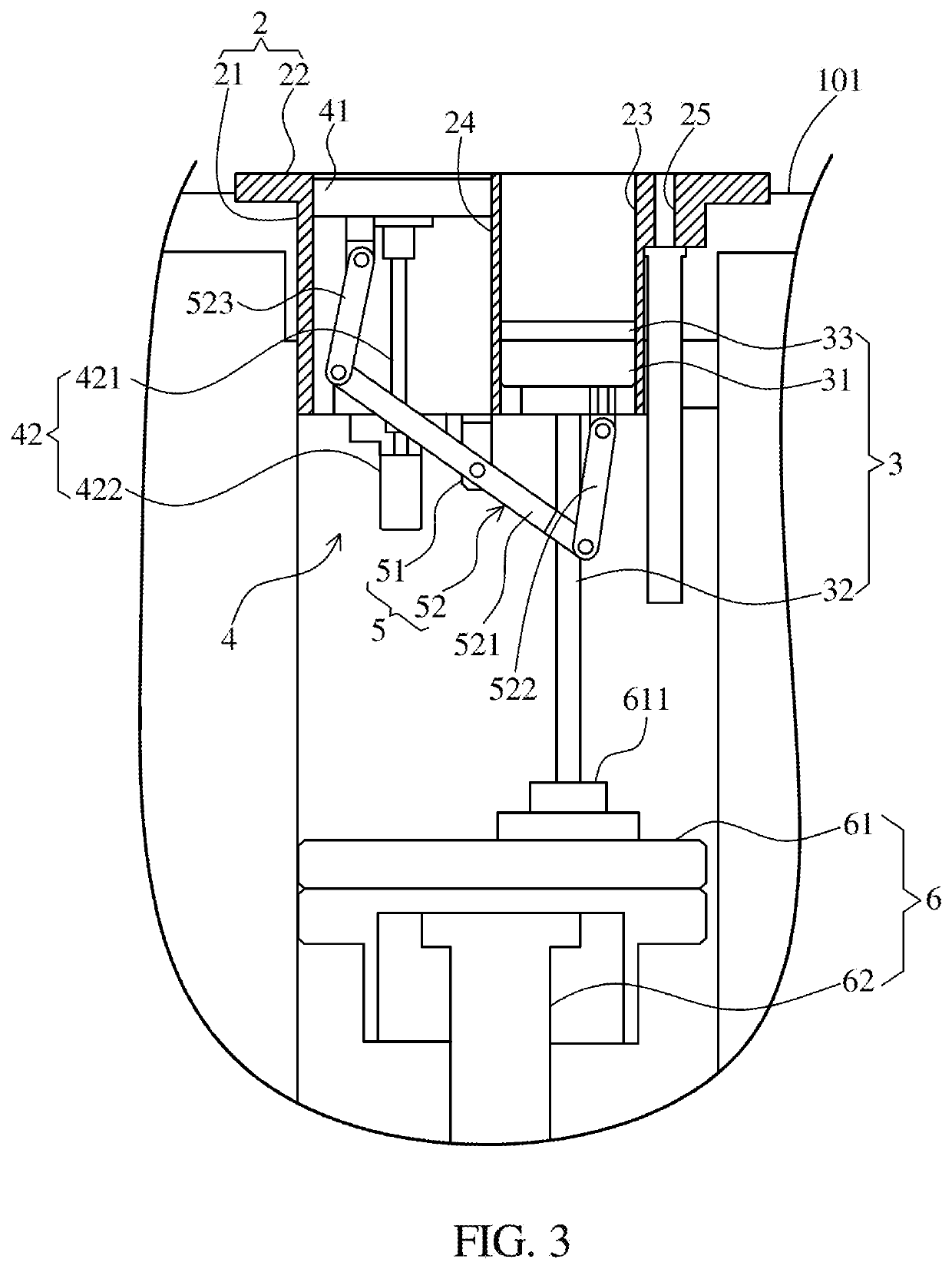
A lifting device for additive manufacturing and an operational method thereof are provided. The lifting device has a base, a processing module, a powder feeding module, a linkage module, and a lifting module. The base is formed with a processing space and a powder feeding space. The processing module has a processing base, and the powder feeding module has a powder feeding base. The processing base and the powder feeding base are driven and moved by the lifting module. Thereby, two power sources of a traditional lifting device can be integrated into a single power source.

Description

CROSS REFERENCE TO RELATED APPLICATIONS[0001]This application claims the priority of Chinese Application No. 201810965584.4, filed on Aug. 23, 2018, the disclosure of which is incorporated herein by reference.FIELD OF INVENTION[0002]The present disclosure relates to a lifting device and an operational method thereof, and in particular to a lifting device for additive manufacturing and an operational method thereof.BACKGROUND OF INVENTION[0003]Additive manufacturing technology is also known as three-dimensional (3D) printing or rapid prototyping technology. It is technology that uses adhesive material (such as powdered metal or plastic) or a fuse to construct an object by stacking up layers based on digital module data. Current commonly-used methods of additive manufacturing include laser powder melting, electron beam powder melting, laser coaxial feeding, and arc fuse shaping technology. Among them, the laser powder melting technology is a new type of additive manufacturing, and doe...

Claims


Application Information

Patent Timeline
Patent Type & Authority Applications(United States)
IPC IPC(8): B29C64/245B33Y10/00B33Y30/00B33Y40/00B29C64/153B29C64/357B29C64/321
CPCB29C64/321B29C64/357B29C64/153B33Y30/00B29C64/245B33Y10/00B33Y40/00B29C64/20B22F10/73B22F10/28B22F12/222B22F12/50Y02P10/25B29C64/232
Inventor KAO, HUAI-ENCHEN, HSIN-PAOYEN, JUI-HSIUNG
Owner TONG-TAI MASCH & TOOL CO LTD
Learn More