
Surgical fastener

a technology of surgical fasteners and screws, which is applied in the field of surgical fasteners, can solve the problems of reducing and reducing the risk of fusion, so as to facilitate fusion, facilitate fusion, and increase the probability of fusion

Active Publication Date: 2022-02-15
BLUE SKY TECHNOLOGIES LLC
View PDF5 Cites 0 Cited by
  • Summary
  • Abstract
  • Description
  • Claims
  • Application Information

AI Technical Summary

Benefits of technology

The current surgical fastener has a thread length of three to ten times longer than traditional surgical screws, providing a larger potential fixation surface area. It can be used in numerous surgeries such as spine, joint, and facial procedures. The frontal edge or tapered tip can separate surfaces or join them, and the cutter can be used to expose bone for bone-to-bone fusion. The surgical fastener can limit the depth of insertion, be connected with other surgical apparatus, and provide increased torque for the cutter. After insertion, rotating the surgical fastener from -30 degrees to -150 degrees can improve its resistance to pull out forces. Overall, this technology achieves improved fixation strength and stability during surgical procedures.

Problems solved by technology

As the diameter of the insertion pathway increases, there is greater risk of the screw backing out and construct failure.
Larger diameter screws are stronger and more difficult to extract due to increased surface area (friction).
The biophysical forces transmitted to these implanted screws can lead to loosening, construct failure, pain and additional revision surgery.

Method used


Image

  • Surgical fastener
  • Surgical fastener
  • Surgical fastener

Examples


Embodiment Construction

[0031]Although the disclosure hereof is detailed to enable those skilled in the art to practice the invention, the embodiments published herein merely exemplify the present invention.

[0032]As used herein, with respect to the surgical fastener (400): 1) “anterior” of the surgical fastener (400) means the side of the surgical fastener most distant from the surgeon and 2) “posterior or surgeon-facing side” of the surgical fastener (400) means the side of the surgical fastener nearest the surgeon.

[0033]In the most general sense, the present invention can result in joint arthrodesis where the surgical fastener is surgically inserted into or across a joint space. Depending on surgical parameters one or more surgical fasteners can be associated with the same surgically created cavity or joint space. The current surgical fastener can be useful for surgeries that can assist in stabilizing injured, deformed and or degenerative joints. Preferred embodiments of the current invention can be empl...


PUM


Abstract

A surgical fastener for use in posterior surgeries that require fusion between the occiput and pelvis. Among other things, the surgical fastener includes a cutter for cutting bone or other tissue.

Description

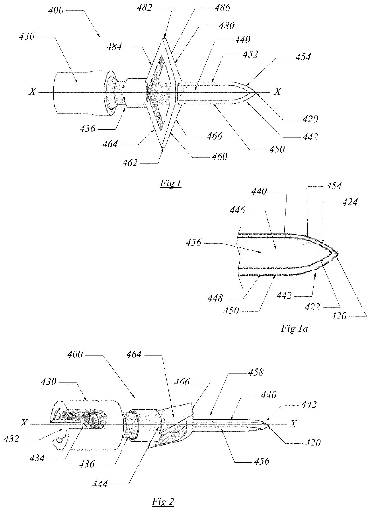
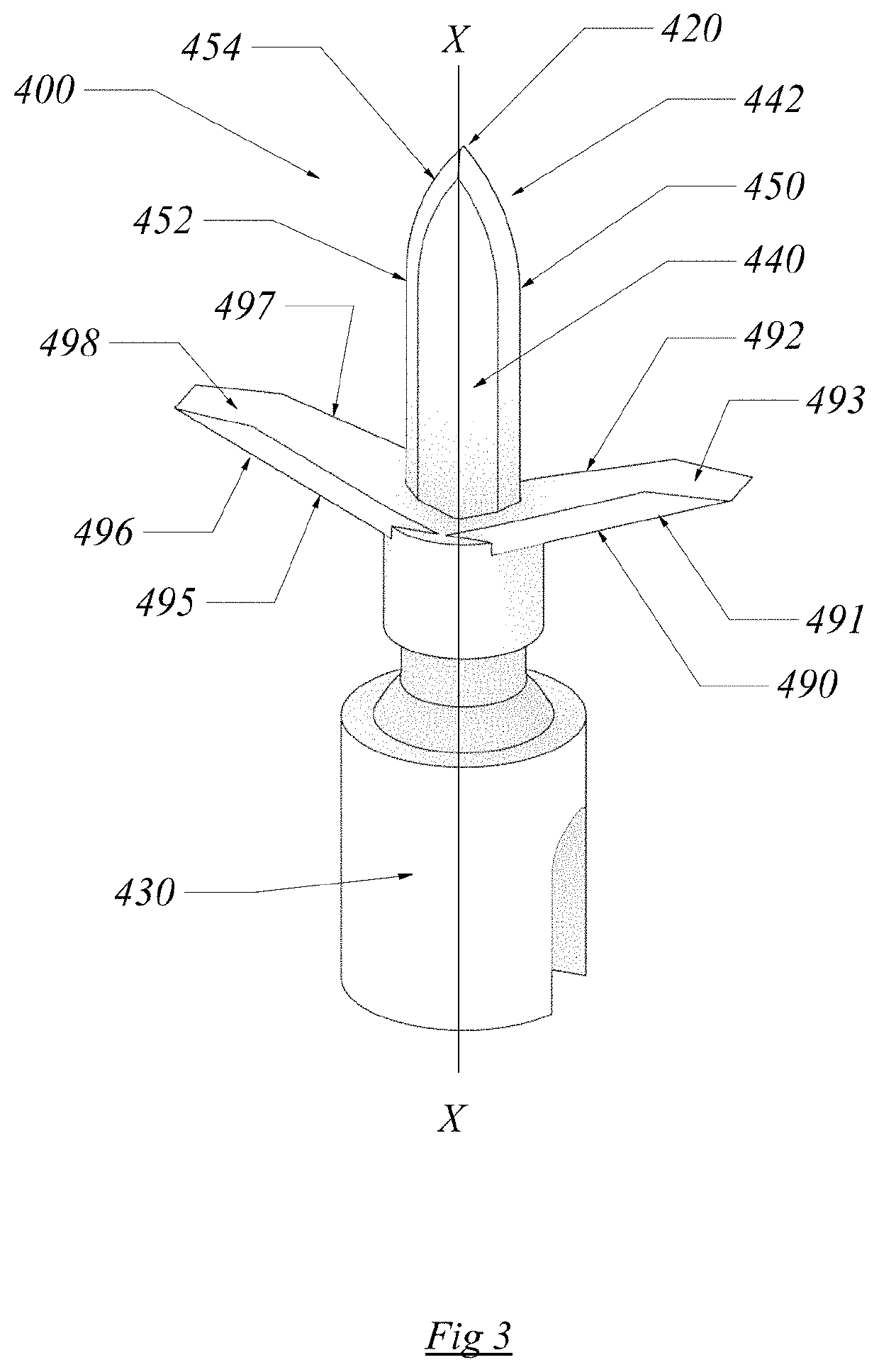
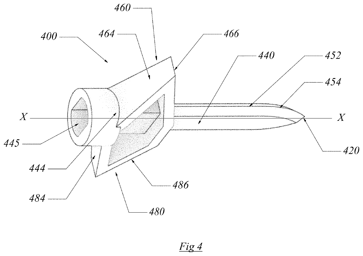
PRIORITY[0001]Applicant claims the benefit of U.S. Provisional Application No. 62 / 975,248—Surgical Fastener—filed on Feb. 12, 2020.BACKGROUND OF THE INVENTIONA. Field of the Invention[0002]The present invention is a surgical fastener provided with an elongate blade having an anterior tapered tip, first and second cutters attached to a centralized segment of the elongate blade and a head. In select preferred embodiments, the head can be fixed or polyaxial. Except for the head, the surgical fastener is threadless.B. Description of the Previous Art[0003]Any discussion of references cited in this Description of the Previous Art merely summarizes the disclosures of the cited references and Applicant makes no admission that any cited reference or portion thereof is relevant prior art. Applicant reserves the right to challenge the accuracy, relevancy and veracity of the cited references.[0004]References that may indicate a state-of-the-art include: 1) U.S. Pat. No. 5,258,002—Jeffers, et al...

Claims


Application Information

Patent Timeline
Patent Type & Authority Patents(United States)
IPC IPC(8): A61B17/16A61B17/84A61B17/70A61B17/86
CPCA61B17/7055A61B17/16A61B17/7035A61B17/84A61B17/8605A61B17/8625A61B17/8635A61B2017/8655A61B17/844A61B17/1617A61B17/7032
Inventor CASTRO, FRANK
Owner BLUE SKY TECHNOLOGIES LLC
Learn More